
PoolMasterproTM PVC Tube Solar Pool Heating System -- Installation and User Manual
These online install instructions are also available in printable pdf form; download here - PoolMasterproTM PVC Tube Solar Pool Heating System -- Installation and User Manual.
Tip: If you need to email us a question about a specific section of this manual, you can use the headings "Get Link" button to copy a hyperlink which will automatically jump to that section when loaded on a browser.
PoolMaster
pro
™ Solar Pool Heating System -- Installation & User Manual
© Copyright 2021 Optex Solar Pty Ltd. All rights strictly reserved.
EcoOnline PoolMaster
pro
™
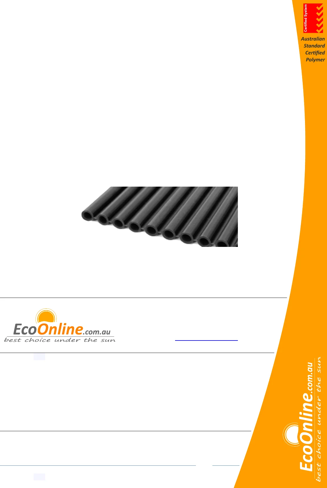
14 Tube PVCn Strip Collector
Solar Pool Heating System
Installation and User Manual - Revised 20/11/2021
Optex Solar Pty. Ltd.
ABN: 88 128 228 884
www.EcoOnline.com.au
email: info@EcoOnline.com.au
© Copyright 2021 Optex Solar Pty Ltd. All rights strictly reserved. This publication is protected by copyright law
and unless otherwise specified is for your personal and non-commercial use only. No part of this publication
may be reproduced or distributed by any process, electronic or otherwise, without the specific written
permission of Optex Solar Pty Ltd. Trademarks appearing in this manual are the sole property of Optex Solar
Pty Ltd or their respective owners. Nothing in this publication shall be construed as granting any express or
implied license to use any intellectual property of Optex Solar Pty Ltd otherwise than for personal and
non-commercial use only. Optex Solar Pty Ltd must not, to the full extent permitted by law, be held liable
for any claim, cost (including legal costs), damage, expense, loss (including fines, penalties, set-offs and
consequential loss) or liability arising from the use (or misuse) of any product described in this
publication, unless expressly provided otherwise in this publication. Information as well as any
products described in this publication are subject to change without notice.

PoolMaster
pro
™ Solar Pool Heating System -- Installation & User Manual
© Copyright 2021 Optex Solar Pty Ltd. All rights strictly reserved.
Page 2
Contents Click Heading Titles to Navigate Up or Down
11.1 Ladder Safety

PoolMaster
pro
™ Solar Pool Heating System -- Installation & User Manual
© Copyright 2021 Optex Solar Pty Ltd. All rights strictly reserved.
Page 3
21.1 Drain Down
21.2 Winterization
PoolMaster
pro
™ Solar Pool Heating System -- Installation & User Manual
© Copyright 2021 Optex Solar Pty Ltd. All rights strictly reserved.
Page 4
25.1 Notes on First Usage
1 Key Terms
Create jump link to this section-- Get Link
This manual was written to follow guidelines and recommendations given in:
AS 3634 - 1989 Solar heating systems for swimming pools
‘HAZPAK’ produced by the work-cover authority
AS 3000 (2007) Sections 6.3, 6.4 & 6.5
Please take the time to read this manual before starting any work. Particular attention should be given to text
contained in the following key terms.
Please note EcoOnline has a strong product safety policy; do not install products without reading safety guidelines in
the manual. Please report any product safety issues or near misses to info@EcoOnline.com.au no matter how trivial.
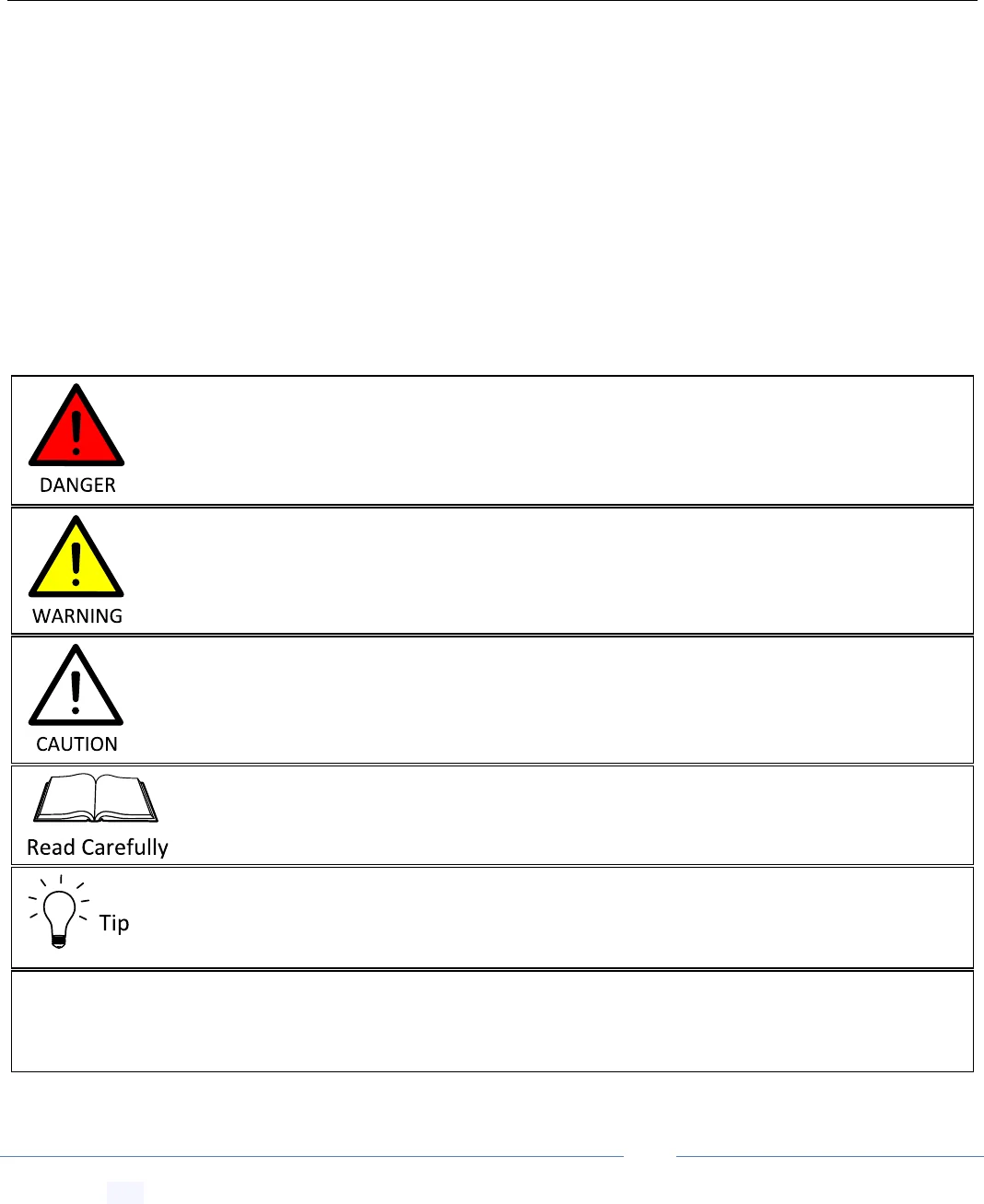
Refers to useful information for the optimal operation of the system
Indicates a SAFETY issue that is likely to cause injury or death if the user does not
follow the instructions.
Indicates a SAFETY issue that may cause injury or death if the user does not follow the
instructions.
Indicates an issue that may cause system component damage if the user does not
follow the instructions.
Refers to critically important information related to the correct functioning of the
system.
Why? Italic text is optional reading. Gives extra information and reasoning for recommendations that are
non-obvious and/or counter intuitive.

PoolMaster
pro
™ Solar Pool Heating System -- Installation & User Manual
© Copyright 2021 Optex Solar Pty Ltd. All rights strictly reserved.
Page 5
2 Pre-Installation Suitability and Safety Checklist
Create jump link to this section-- Get Link
The following outlines mandatory suitability and safety requirements for installing this solar heating system. Please
read carefully, if any of the following requirements cannot be meet the system should NOT be purchased or
installed.
Due to the potential of falling from heights, mounting the solar strip collectors on a roof or
structure at heights should only be undertaken by a professional installer, unless you are
accustomed to and confident of performing the work safely. We strongly recommend the
installer invests in roof safety guard rails and a safety harness system, especially for DIY
applications.
Building regulations vary from state to state and MUST override any instructions supplied in
this manual. It is the responsibility of the purchaser/installer to check that installations
comply with any relevant state laws and regulations.
Collectors are to be used with chlorinated (or otherwise sanitized) pool water ONLY. Do not
use collectors to heat fresh (untreated) water due to the potential for Legionaries bacteria
build up.
This appliance is not intended for use by persons (including children) with reduced physical,
sensory or mental capabilities, or lack of experience and knowledge, unless they have been
given supervision or instruction concerning use of the appliance by a person responsible for
their safety. Children should be supervised to ensure that they do not play with the appliance.
PoolMaster
pro
™ Solar Pool Heating System -- Installation & User Manual
© Copyright 2021 Optex Solar Pty Ltd. All rights strictly reserved.
Page 6
3 Warranties
Create jump link to this section-- Get Link
EcoOnline™ offers the following Warranties
15 Year pro-rata Warranty on all strip collectors
2 year Warranty on Davey Pool Pumps
3 Year Warranty on Dontek and Ascon Controllers
See our Terms and Conditions page for further details: www.EcoOnline.com.au/terms-and-conditions
4 Collector Sizing Guide
Create jump link to this section-- Get Link
An interactive collector sizing calculator and pool water temperature simulator can be found on our website at:
www.EcoOnline.com.au/pool-heating-sizing-calculator
www.EcoOnline.com.au/pool-water-temperature-simulator
4.1 A Word on Transparent Bubble Pool Covers
Create jump link to this section-- Get Link
EcoOnline recently carried out a full pool heating loading technical study including performance data on transparent
bubble pool covers. We found that while transparent pool covers produce a moderate heating effect by themselves,
they produced a much larger pool temperature boost when used in conjunction with a solar pool heater due to
synergistic effects. So much so that if you’re running a solar pool heater and not using a pool cover you are missing
out on surprisingly large temperature gains - see link below for the summaries:
www.EcoOnline.com.au/how-warm-can-a-pool-get-with-a-solar-heater-and-cover
So if you’ve used a pool cover before and had disappointing results, we highly recommend you try using a cover
again after you install our solar pool heating system.
Customer please note: WARRANTY IS VOID if collectors are installed:
without a vacuum release valve on the return line,
or a non-return valve on the solar pump outlet (with 6mm drain hole in flap),
or without a by-pass valve on a grossly oversized pump,
or with water pH less than 7.2,
or without the supplied strainer (for systems independent of the main filter),
or if the collectors are installed below the water level.
Why? Such installations will expose the collectors to debris build up, strong fatiguing
positive/negative pressures and/or chemical attack from hot water. These situations will
have detrimental effects on the collectors which will limit lifetimes.
Only highly transparent clear and light blue solar blankets increase water
temperatures; silver backed or non-transparent solar blankets reject sunlight and will
substantially cool your pool - this is irrespective of whether or not the silver side faces
up or down. Non-transparent blankets are okay to use for 100% shaded pools only.
PoolMaster
pro
™ Solar Pool Heating System -- Installation & User Manual
© Copyright 2021 Optex Solar Pty Ltd. All rights strictly reserved.
Page 7
5 Pool Chemistry Compatibility Guide
Create jump link to this section-- Get Link
6 Pump Sizing Guide
Create jump link to this section-- Get Link
6.1 A Word on Pump Sizing Choice
Create jump link to this section-- Get Link
The quick reference tables below outline Australian Standard pump sizing recommendations.
There is a range of pump powers one can choose from. If thermal system efficiency is important then choose a pump
at the high end to produce a high flow rate; take care not to over-pressurize your system (see Optimizing Collector
Pressure below). If electrical efficiency (COP factor) is important to you then choose a pump near the lowest power
range. To help you understand the potential savings from such choices we have created an interactive pump sizing
simulator which can be found on our website at:
www.ecoonline.com.au/sizing-calculators/poolmasterpro-strip-pool-heating-pump-sizing
However, if you go with a lower power pump you’ll need the following:
A slightly larger collector area; the pump sizing calculator will let you know by how much.
You will need to check with the pump manufacture that your chosen pump can still prime reliably at your
pump height.
We highly recommend you use a by-pass line to help your pump to prime reliably, see Installing a By-Pass
Tube or By-Pass Ball Valve below.
Lastly you may need to run your main filter pump in the afternoon to help mix the warm water if your pool
volume turnover falls below the 50% - 75% range.
6.2 Quick Reference Solar Pump Sizing for Independent Systems
Create jump link to this section-- Get Link
The two tables below will give you the minimum and maximum Australian Standard pump power recommendations
for independent type systems in input watts (not output watts), these specs should be marked on the pump.
Minimum Recommended Pump Power is Limited by Water Turn-Over Requirements
Pool
Water Volume
Minimum
Recommended Flow
For 1
st
Story Install (3m):
Minimum Input Watts Required
For 2
nd
Story Install (6m):
Minimum Input Watts Required
20,000 L
50 L/min
270 Watts (0.36 HP)
350 Watts (0.47 HP)
25,000 L
63 L/min
290 Watts (0.39 HP)
370 Watts (0.50 HP)
30,000 L
75 L/min
320 Watts (0.42 HP)
400 Watts (0.53 HP)
35,000 L
88 L/min
340 Watts (0.46 HP)
420 Watts (0.56 HP)
40,000 L
100 L/min
370 Watts (0.49 HP)
450 Watts (0.60 HP)
45,000 L
113 L/min
390 Watts (0.52 HP)
470 Watts (0.63 HP)
50,000 L
125 L/min
420 Watts (0.56 HP)
500 Watts (0.67 HP)
55,000 L
138 L/min
450 Watts (0.60 HP)
530 Watts (0.71 HP)
This system is not compatible with acidic pool/spa water (pH less than 7.2). Sodium
Carbonate must be added to protect the system from acidic pH (<7). pH should be maintained
between 7.2-7.8 for maximum system longevity.
Why? Acidic water with pH less than 7.0 has excess free H+ ions which like to bond to and
hence break apart polymer carbon and silicon bonds.
PoolMaster
pro
™ Solar Pool Heating System -- Installation & User Manual
© Copyright 2021 Optex Solar Pty Ltd. All rights strictly reserved.
Page 8
60,000 L
150 L/min
470 Watts (0.64 HP)
560 Watts (0.75 HP)
65,000 L
163 L/min
500 Watts (0.68 HP)
590 Watts (0.79 HP)
70,000 L
175 L/min
530 Watts (0.72 HP)
620 Watts (0.83 HP)
75,000 L
188 L/min
570 Watts (0.76 HP)
660 Watts (0.88 HP)
80,000 L
200 L/min
600 Watts (0.80 HP)
690 Watts (0.93 HP)
If you don’t know your pools water volume you can look it up from the table supplied below based on the total
water area and average depth:
Maximum Recommended Pump Power is Limited by Collector Pressure
Collectors
Gross Area
Maximum
Recommended Flow
For 1
st
Story Install (3m):
Maximum Input Watts
For 2
nd
Story Install (6m):
Maximum Input Watts
13 m
2
67 L/min
340 Watts (0.47 HP)
450 Watts (0.61 HP)
17 m
2
83 L/min
380 Watts (0.51 HP)
480 Watts (0.65 HP)
20 m
2
100 L/min
410 Watts (0.55 HP)
520 Watts (0.69 HP)
23 m
2
117 L/min
450 Watts (0.60 HP)
550 Watts (0.74 HP)
27 m
2
133 L/min
490 Watts (0.65 HP)
590 Watts (0.79 HP)
30 m
2
150 L/min
530 Watts (0.70 HP)
630 Watts (0.85 HP)
33 m
2
167 L/min
570 Watts (0.76 HP)
670 Watts (0.90 HP)
37 m
2
183 L/min
610 Watts (0.82 HP)
720 Watts (0.97 HP)
40 m
2
200 L/min
660 Watts (0.88 HP)
770 Watts (1.03 HP)
43 m
2
217 L/min
700 Watts (0.94 HP)
820 Watts (1.10 HP)
47 m
2
233 L/min
750 Watts (1.00 HP)
870 Watts (1.17 HP)
50 m
2
250 L/min
800 Watts (1.08 HP)
930 Watts (1.24 HP)
53 m
2
267 L/min
860 Watts (1.15HP)
980 Watts (1.32 HP)
6.3 Example Pump Sizing
Create jump link to this section-- Get Link
For example, for a large 75,000 Litre pool and 1st story roof your minimum Australian Standard pump specs from
the first table above are 566 Input Watts. If you want to install a 40 m
2
collector area for this pool for example, your
maximum pump specs, from the second table above are 656 Input Watts. Pumps well below the minimum specs
Pool Water area vs Average Depth Conversion Table
Average depth
Waters Area
1.3 m
1.4 m
1.45 m
1.5 m
1.55 m
1.6 m
1.65 m
1.7 m
1.8 m
10 m
2
13000 L
14000 L
14500 L
15000 L
15500 L
16000 L
16500 L
17000 L
18000 L
15 m
2
19500 L
21000 L
21750 L
22500 L
23250 L
24000 L
24750 L
25500 L
27000 L
20 m
2
26000 L
28000 L
29000 L
30000 L
31000 L
32000 L
33000 L
34000 L
36000 L
25 m
2
32500 L
35000 L
36250 L
37500 L
38750 L
40000 L
41250 L
42500 L
45000 L
30 m
2
39000 L
42000 L
43500 L
45000 L
46500 L
48000 L
49500 L
51000 L
54000 L
35 m
2
45500 L
49000 L
50750 L
52500 L
54250 L
56000 L
57750 L
59500 L
63000 L
40 m
2
52000 L
56000 L
58000 L
60000 L
62000 L
64000 L
66000 L
68000 L
72000 L
45 m
2
58500 L
63000 L
65250 L
67500 L
69750 L
72000 L
74250 L
76500 L
81000 L
50 m
2
65000 L
70000 L
72500 L
75000 L
77500 L
80000 L
82500 L
85000 L
90000 L
55 m
2
71500 L
77000 L
79750 L
82500 L
85250 L
88000 L
90750 L
93500 L
99000 L
PoolMaster
pro
™ Solar Pool Heating System -- Installation & User Manual
© Copyright 2021 Optex Solar Pty Ltd. All rights strictly reserved.
Page 9
may not be strong enough to turn over a sufficient volume of water - while oversized pumps are more expensive to
run for little extra heat gain and may need a ball valve constriction installed depending on the collector’s internal
pressure.
6.4 Solar Pump Sizing for Booster Systems
Create jump link to this section-- Get Link
6.5 Filter Pump Sizing for Manual Systems
Create jump link to this section-- Get Link
7 Solar Line PVC Pipe Sizing Guide
Create jump link to this section-- Get Link
The table below will help you choose the correct size PVC pipe for the solar lines running to and from your roof. On
the roof we generally recommend 40 PVC (DN40) to match the manifolds. Coming down the roof the pipe size can
then be adapted to the pipe size you have for your solar line ground run i.e. 40 PVC (DN40) or 50 PVC (DN50).
Recommended PVC Piping Sizing for Solar Pool Heating System Lines
Anticipated Flow Rate
Absolute Minimum
Ideal PVC Pipe Size
Maximum Pipe Size
70 Litres/min
20 PVC (DN20)
25 PVC (DN25)
32 PVC (DN32)
120 Litres/min
25 PVC (DN25)
32 PVC (DN32)
40 PVC (DN40)
200 Litres/min
32 PVC (DN32)
40 PVC (DN40)
50 PVC (DN50)
250 Litres/min
40 PVC (DN40)
50 PVC (DN50)
65 PVC (DN65)
400 Litres/min
50 PVC (DN50)
65 PVC (DN65)
80 PVC (DN80)
880 Litres/min
80 PVC (DN80)
100 PVC (DN100)
125 PVC (DN125)
For booster type systems you should choose a pump at or just below the minimum
specs in the table above. Why? The take off point for solar is already pressurized by the
filter pump, hence a smaller pump should be used.
For manual type systems running off a main pool filter pump, please check that the filter
pump is large enough to accommodate the extra load of supplying water to the collectors
at the required pump height + a 1 meter pressure drop across the collector array. Why?
Filter pumps are geared for flow, not pump height, solar pumps are geared specifically for
roof solar applications.
If the distance from the pool to the roof collector area is more than 10m we recommend
you use the next size up PVC pipe.
PoolMaster
pro
™ Solar Pool Heating System -- Installation & User Manual
© Copyright 2021 Optex Solar Pty Ltd. All rights strictly reserved.
Page 10
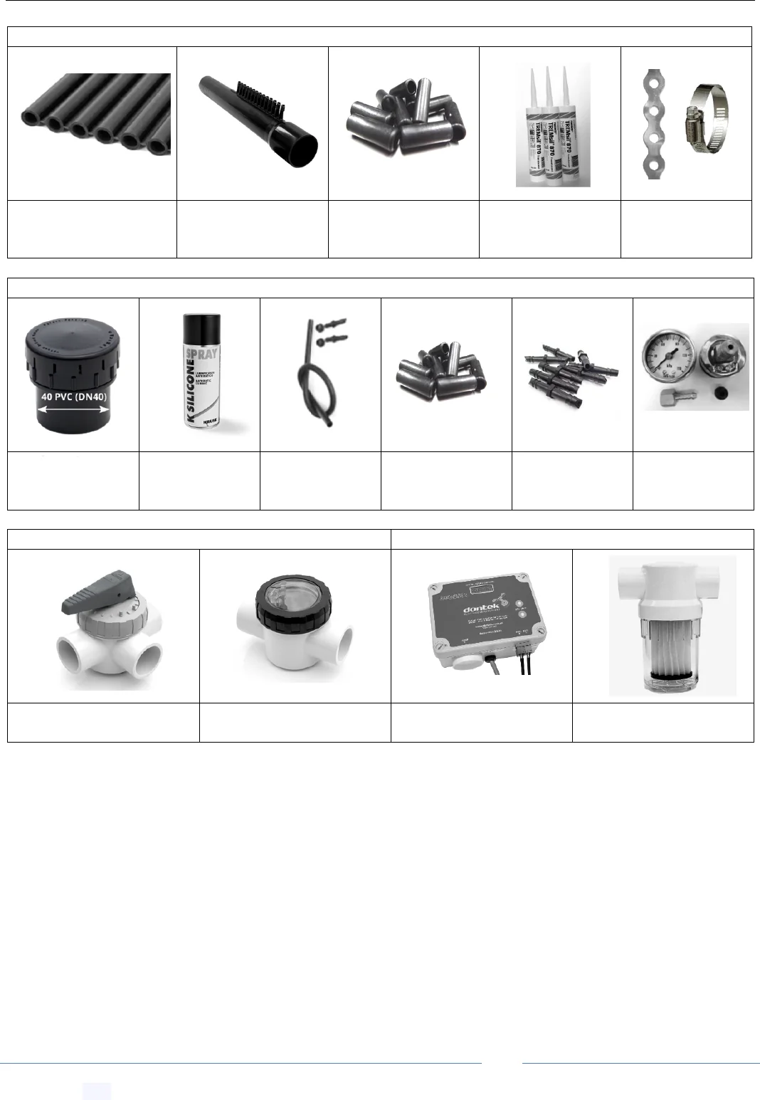
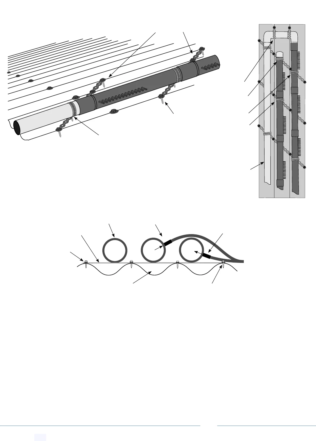
8 Collector Array Components
Create jump link to this section-- Get Link
1 × 4m
2
Strip Collector Kit (number of kits depends on system purchased)
1 × 25m 14 tube PVC
nitrile 165mm
strip role
2 × 40 PVC (DN40)
PVC Manifold -
500mm x 14 Tube
28 × tube locking
collars
1 × silicon tube
per 4m
2
kit
1 × Pipe clamp +
0.5m band for
fixing per 4m
2
kit
Other Essential System Components (depending on system purchased)
1 × 40 PVC
Vacuum breaker
valve
1 × Can of
silicon lubricant
spray
1 × Drain Down
Kit
2 × 28 locking
collar for
repair kit
1 × 14 joining
barb repair
kit
1 × In-line
pressure gauge
For Manual Systems (depending on purchase)
For Independent Systems (depending on purchase)
1 × 40 PVC (DN40) PVC 3-
way Ball valve
1 × 40 PVC (DN40) Spring
loaded non-return valve
1 × Dontek Controller
1 × 40 PVC (DN40) PVC
strainer
PoolMaster
pro
™ Solar Pool Heating System -- Installation & User Manual
© Copyright 2021 Optex Solar Pty Ltd. All rights strictly reserved.
Page 11
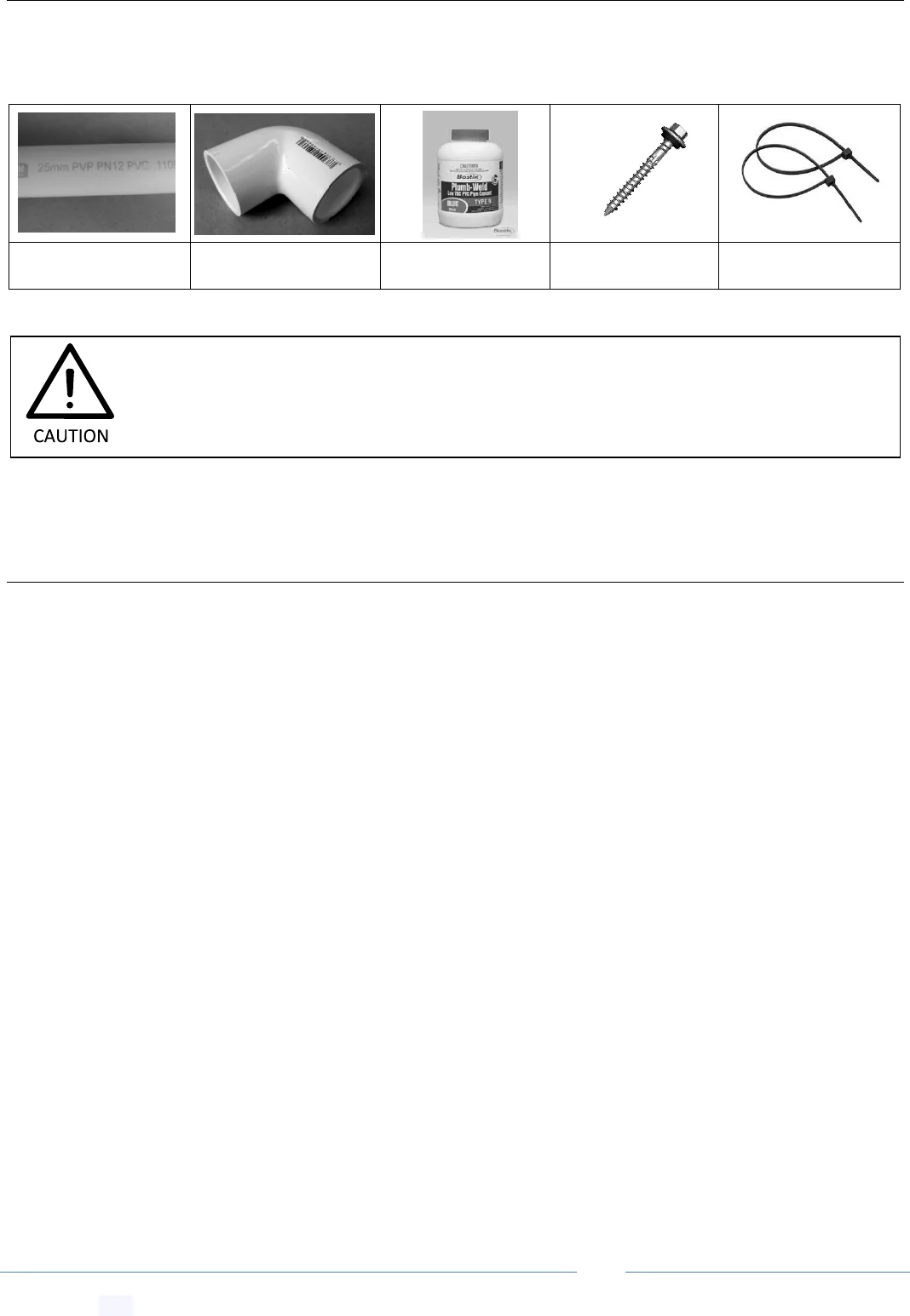
9 Required Components (Not Supplied)
Create jump link to this section-- Get Link
You also require some of the following extra items depending on your system. These are available in any plumbing or
hardware store.
10 Required Tools
Create jump link to this section-- Get Link
- Battery powered hand drill
- Screwdriver
- Safety glasses
- Corking gun (for Silicon glue)
- Hack saw
- Gloves
- Personal Sun/UV protection
- Assorted drill bits
- Power Lead
- Heat Gun
- Tape measure
- Tin snips
- Industrial Ladder
- Needle nose pliers
- Power Lead
- Scissors
- Old cloth for silicon over spray
- Hammer
Appropriate PVC
piping
Various PVC
plumbing bits
N & P-type PVC
cement & primer
Fixing screws for
perforated band
Cable ties for fixing
thermostat wire
We recommend AS 1477 compliant PVC piping with PN9 pressure rating or greater and
matching PVC fittings be used for all collector array plumbing.
PoolMaster
pro
™ Solar Pool Heating System -- Installation & User Manual
© Copyright 2021 Optex Solar Pty Ltd. All rights strictly reserved.
Page 12
11 Safety When Working at Heights
Create jump link to this section-- Get Link
The installer should always take the necessary safety precautions:
Choose an appropriate day: cool, dry, calm and partly cloudy.
Plan out your install: make sure you have all required components, tools and have plenty of allocated time.
Only work at heights when you are well rested and alert.
Never work alone, always work with at least one other person.
Always use a safety harness or fall arrest system attached to appropriate roof anchor points.
Wear clothes that fit well but that do not restrict movement.
Use proper non-slip shoes.
Use sunscreen.
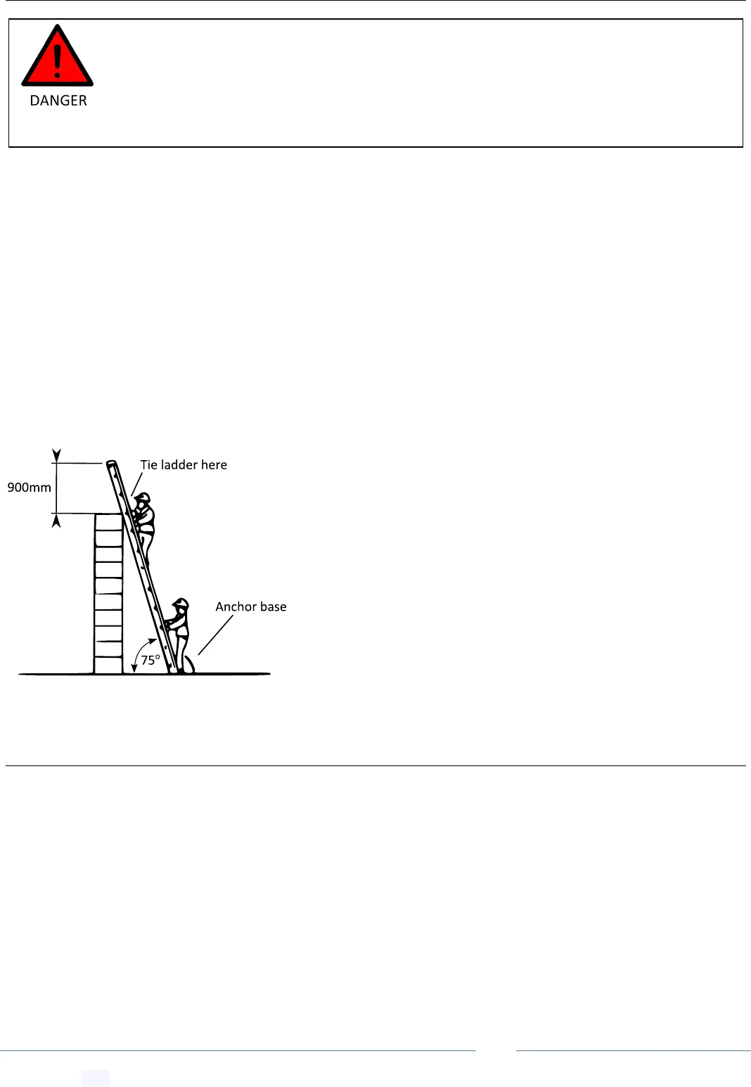
11.1 Ladder Safety
Create jump link to this section-- Get Link
The chance of a falling from a ladder should never be
underestimated. Use only solid industrial grade ladders in good repair
that have been checked for faults.
Note: even a small unexpected movement of the ladder, such as a
small slip, can cause loss of balance and result in a fall.
The ladder should be placed on solid ground and should ALWAYS be
securely anchored at the base and secured at the top to prevent
slipping.
12 Choosing a Place to Install the Collector Array
Create jump link to this section-- Get Link
When choosing a location for your collector array you should consider the following in order of importance:
Shading - the collector array should receive no shading between the hours 10am to 4pm.
Direction - collectors should preferably face north for maximum heat collection; however the collector
array can also face any angle between East to West.
Wind - the collector array should be mounted in a relatively sheltered location as much as possible.
Mounting elevation - this depends on the desired seasonal heat collection. Flatter elevations (< 45°) collect
more heat in the summer while installations closer to vertical (> 45°) produce more heat during
spring/autumn.
WHEN WORKING AT HEIGHTS - SAFETY COMES FIRST. A person can easily fall off a ladder
or roof and be seriously injured. For installations on a roof pitch greater than 22° and/or a
double story house we strongly recommend a highly competent professional installer install
your solar collector array. We strongly recommend the installer invests in roof safety guard
rails and a safety harness system, especially for DIY applications.
PoolMaster
pro
™ Solar Pool Heating System -- Installation & User Manual
© Copyright 2021 Optex Solar Pty Ltd. All rights strictly reserved.
Page 13
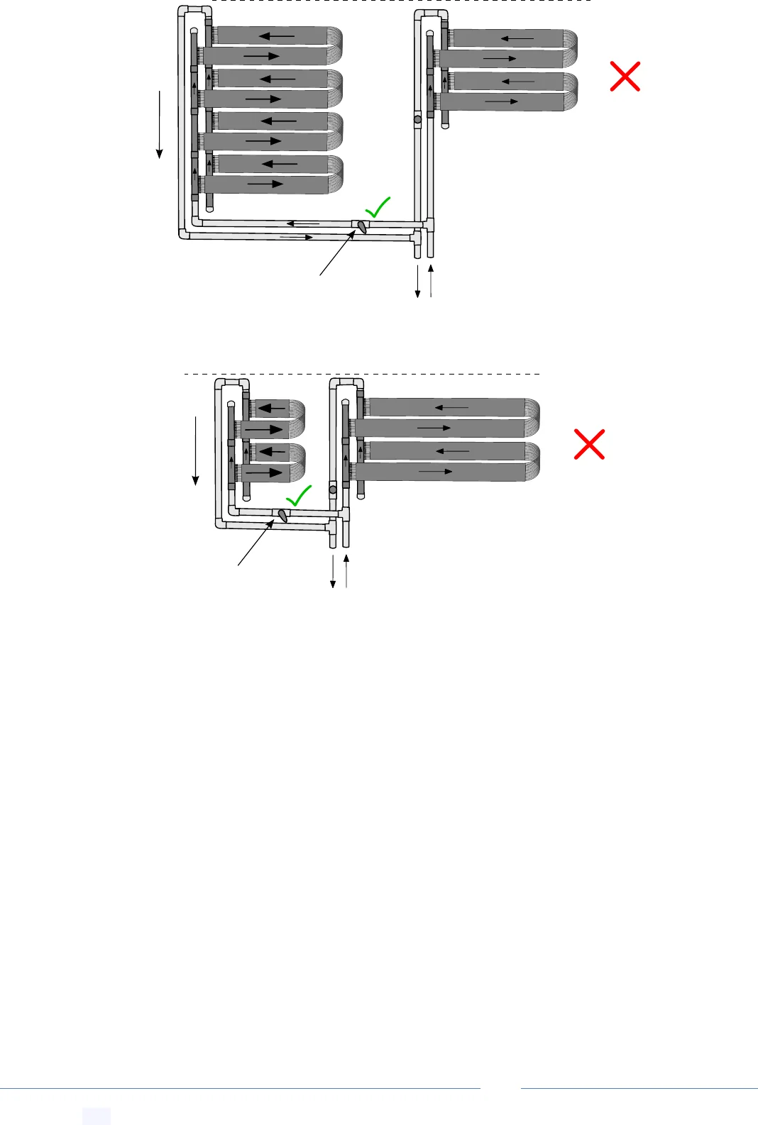
13 Collector Water Flow Configurations
Create jump link to this section-- Get Link
The collector array can face anywhere from West to East, with an optimal orientation of
North for most areas. South facing orientations are generally not recommended, unless
the roof pitch is quite flat < 5˚ for southern states and < 15˚ for northern states.
All collector array configurations must be installed with a vacuum release valve on the
return line and a non-return valve on the pump side.
PoolMaster
pro
™ Solar Pool Heating System -- Installation & User Manual
© Copyright 2021 Optex Solar Pty Ltd. All rights strictly reserved.
Page 14
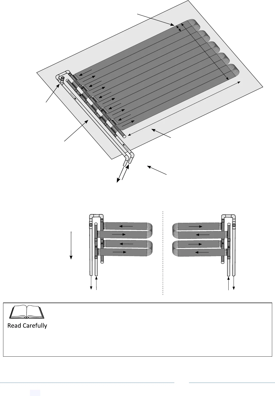
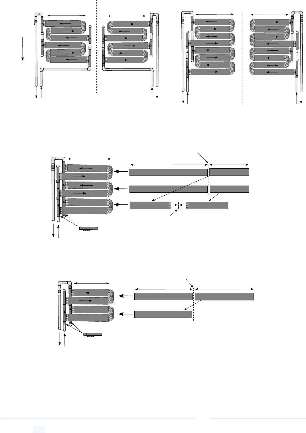
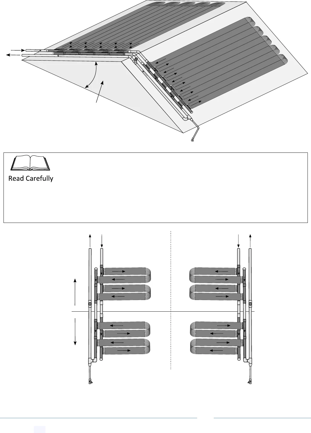
13.1 Bottom Feed Basic (Square, Parallelogram or Trapezoid)
Create jump link to this section-- Get Link
Balance pipe acts
as return to pool
From
pool
To
pool
Vacuum
release
(should point
upwards)
The maximum length of a single
absorber run (up and back)
should not exceed 25m
~12.5m max length
Mirror Image
roof
slope
fall
Width = 165mm + required
gap (0-60mm) per strip
As a general principle for all configurations, water flow in the manifold supply and return
pipe MUST always flow in the same direction to achieve balanced water flow in each
strip. Either up the roof for bottom feed system or down the roof for top feed systems.
Why? Without the third balance pipe water always takes the shortest path, reducing
flow in the higher tube strips.
PoolMaster
pro
™ Solar Pool Heating System -- Installation & User Manual
© Copyright 2021 Optex Solar Pty Ltd. All rights strictly reserved.
Page 15
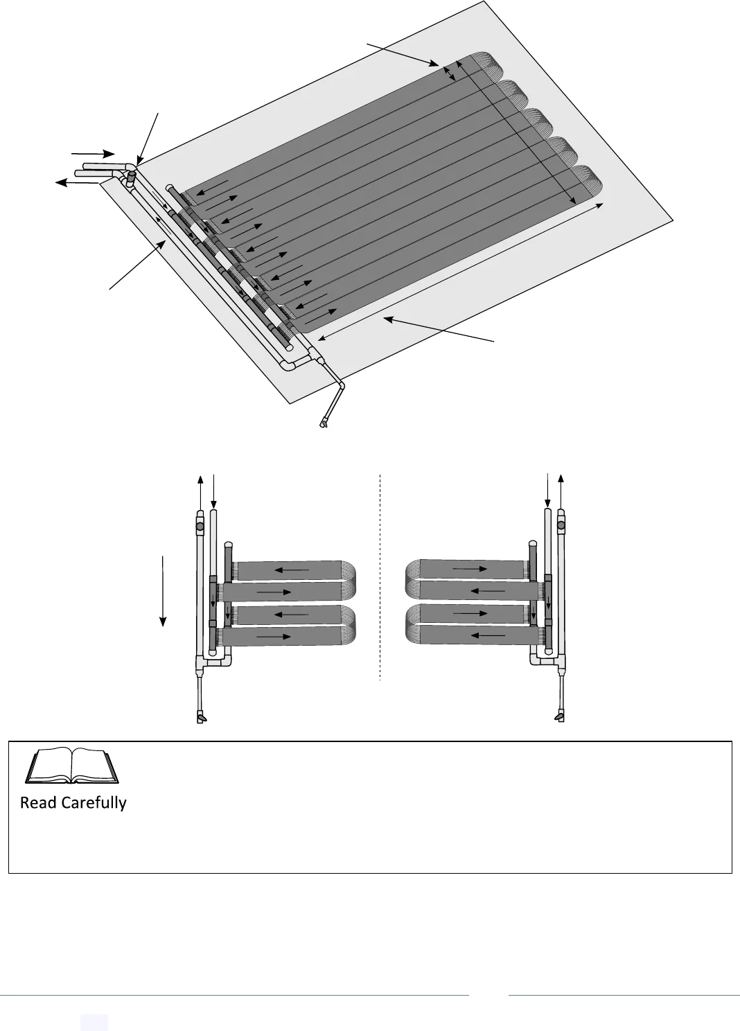
13.2 Top Feed Basic (Square, Parallelogram or Trapezoid)
Create jump link to this section-- Get Link
From pool
To pool
Mirror Image
roof
slope
fall
The maximum length of a single
absorber run (up and back)
should not exceed 25m
~12.5m max length
Vacuum release
(should point upwards)
Balance pipe acts
as return to pool
Width = 165mm + required
gap (0-60mm) per strip
winterization draindown line (for frost prone areas)
winterization draindown line
(for frost prone areas)
Top feed configurations should operate at lower pressure of 50 kPa max, and are not
recommended for areas subject to freezing conditions overnight.
Why? It is impossible for the water to drain full from a top feed system. Freezing
conditions with excess water inside piping can lead to PVC pipes cracking.
PoolMaster
pro
™ Solar Pool Heating System -- Installation & User Manual
© Copyright 2021 Optex Solar Pty Ltd. All rights strictly reserved.
Page 16
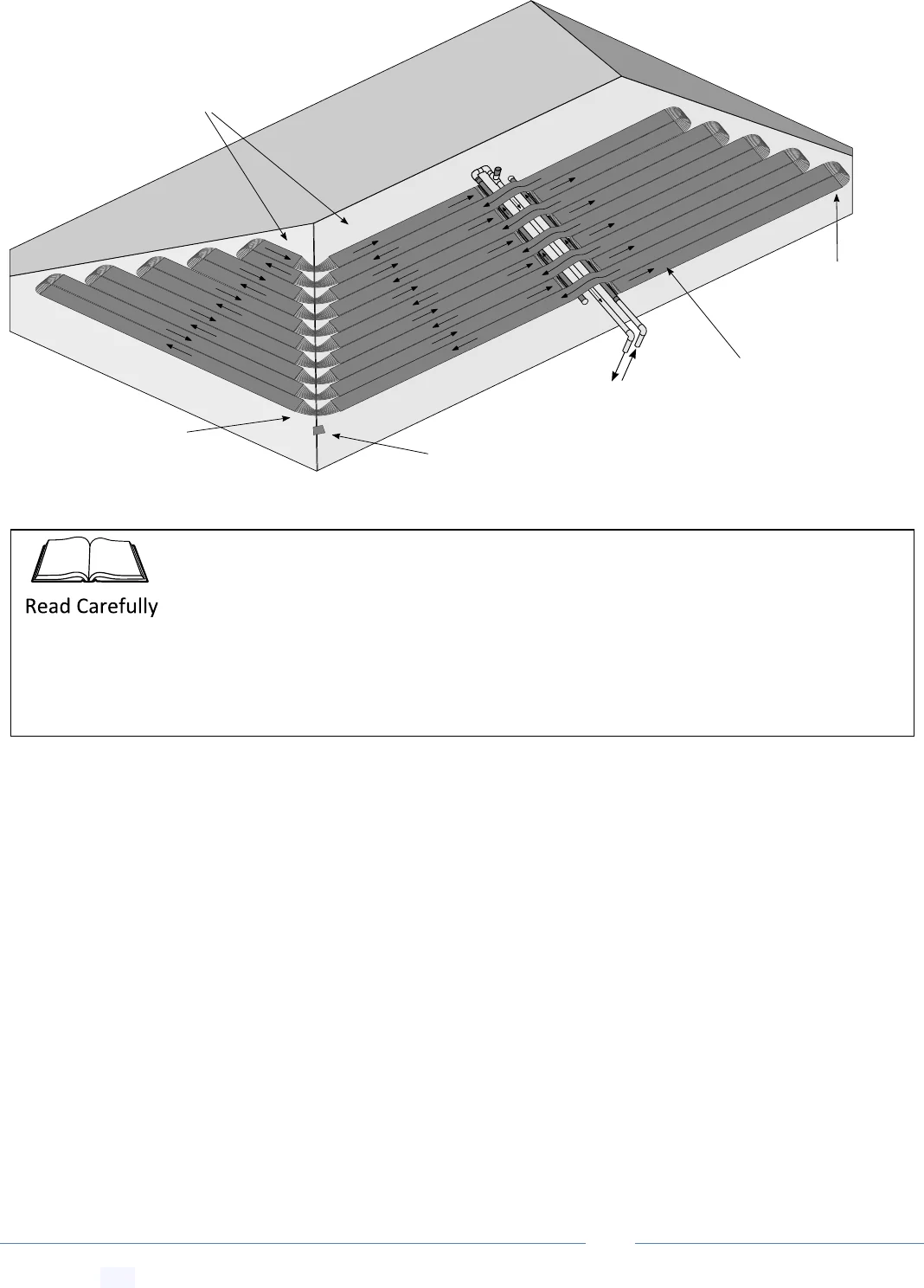
13.3 Narrow Roof Space Multi-Loop Configuration
Create jump link to this section-- Get Link
13.4 Narrow Roof Space Extra Manifolds Configuration
Create jump link to this section-- Get Link
~ 6.25 meters
roof
slope
fall
~ 8.33 meters
~ 8.33 meters
Mirror Image
~ 6.25 meters
Mirror Image
~ 8.33 meters
8.33m off-cut
~16.66 meters
~8.33 meters
8.33m off-cut
Cut 25 meter roles into 2/3rds
join
8.33m off-cut
8.33m off-cut
8.33m off-cut
2 x extra set of manifolds required*
1 x 14 barb extra joiner set required*
* purchase separately
~ 6.25 meters
~12.5 meters
~12.5 meters
12.5m off-cut
Cut 25 meter role in half
12.5m off-cut
12.5m off-cut
2 x extra set of manifolds required*
* purchase separately
8.33m off-cut
PoolMaster
pro
™ Solar Pool Heating System -- Installation & User Manual
© Copyright 2021 Optex Solar Pty Ltd. All rights strictly reserved.
Page 17
13.5 Other Custom Narrow Roof Space Extra Manifolds Configurations
Create jump link to this section-- Get Link
Up and back loops - manifold on one side array
Array
Length
Manifold Count*
(per role)
Array Width**
(per role)
8.33 m
3 (1 extra required)
525 mm
6.25 m
4 (2 extra required)
700 mm
5.0 m
5 (3 extra required)
875 mm
4.167 m
6 (4 extra required)
1050 mm
3.571 m
7 (5 extra required)
1225 mm
3.125 m
8 (6 extra required)
1400 mm
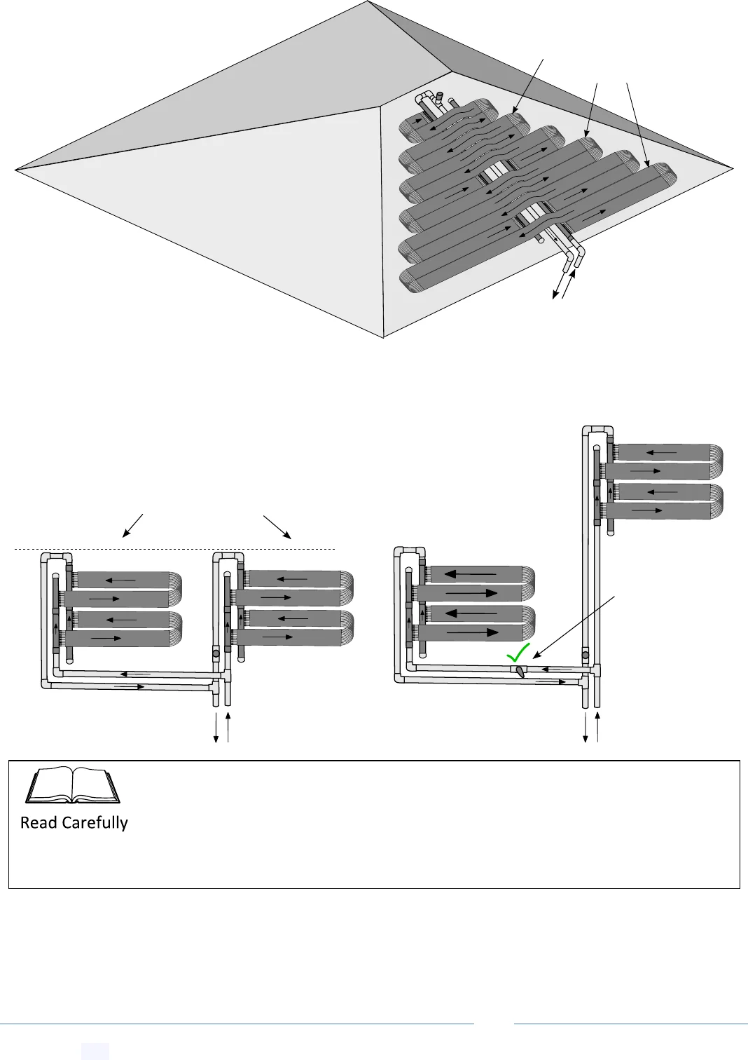
13.6 Double Manifold High Flow Narrow Roof Space Configuration
Create jump link to this section-- Get Link
Straight strips runs - manifolds on both sides
Array
Length
Manifold Count*
(per role)
Array Width**
(per role)
12.5 m
4 (2 extra required)
350 mm
8.33 m
6 (4 extra required)
525 mm
6.25 m
8 (6 extra required)
700 mm
5.0 m
10 (8 extra required)
875 mm
4.167 m
12 (10 extra required)
1050 mm
From
pool
To
pool
Array
Width
Array Length Required
The extra manifold configuration is recommended over the multi-loop configuration due
to the extra flow, however you will need to purchase extra pairs of manifolds and extra
joiner sets (if required).
Why? The extra flow from increasing the manifold count improves system efficiency as
well as lowering back pressure on the pump and collector tubes.
PoolMaster
pro
™ Solar Pool Heating System -- Installation & User Manual
© Copyright 2021 Optex Solar Pty Ltd. All rights strictly reserved.
Page 18
13.7 Bottom Feed Overlap (Square, Parallelogram or Trapezoid)
Create jump link to this section-- Get Link
13.8 Top Feed Overlap (Square, Parallelogram or Trapezoid Layout)
Create jump link to this section-- Get Link
From
pool
To
pool
~12.5m max length
Mirror Image
The maximum length of a single
absorber run (up and back)
should not exceed 25m
roof
slope
fall
Mirror Image
roof
slope
fall
winterization draindown line (for frost prone areas)
Top feed configurations should operate at lower pressure of 50 kPa max, and are not
recommended for areas subject to freezing conditions overnight.
Why? It is impossible for the water to drain full from a top feed system. Freezing
conditions with excess water inside piping can lead to PVC pipes cracking.
PoolMaster
pro
™ Solar Pool Heating System -- Installation & User Manual
© Copyright 2021 Optex Solar Pty Ltd. All rights strictly reserved.
Page 19
13.9 Bottom Feed Butterfly (for long 25m collector arrays)
Create jump link to this section-- Get Link
13.10 Top Feed Butterfly (for long 25m collector arrays)
Create jump link to this section-- Get Link
From
pool
To
pool
~12.5m max length
Mirror Image
~12.5m max length
roof
slope
fall
Mirror Image
roof
slope
fall
winterization draindown line (for frost prone areas)
PoolMaster
pro
™ Solar Pool Heating System -- Installation & User Manual
© Copyright 2021 Optex Solar Pty Ltd. All rights strictly reserved.
Page 20
13.11 Multi-Directional Opposing Bottom and Top Feed Arrays
Create jump link to this section-- Get Link
From pool
To pool
Directionally opposing arrays
are okay for roof pitch no
greater than 15°
<15°
winterization draindown line
(for frost prone areas)
Mirror Image
roof
slope
fall
roof
slope
fall
winterization draindown line (for frost prone areas)
Collector arrays that face opposing compass directions are not recommended unless
the roof pitch is less than ~15˚. In this case the temperature sensor should be installed
at an angle that is an average of the two collector array directions. Installations with a
purely south facing facet are still not recommended for southern areas of Australia.
Why? Depending on the location of the roof sensor the controller could turn the system
on with one bank of collectors in full shade.
PoolMaster
pro
™ Solar Pool Heating System -- Installation & User Manual
© Copyright 2021 Optex Solar Pty Ltd. All rights strictly reserved.
Page 21
13.12 Multi-Directional Curve Around Arrays
Create jump link to this section-- Get Link
From
pool
To
pool
The maximum length of
the longest absorber run
(up and back) should
not exceed ~30m
All configurations can
have loop extension to fill
roof space as required
Corrector facets facing different
compass directions can only be
installed on flat roofs
(pitch 30° or below)
Strips loops can go around
roof edges and roof valleys
Roof thermostat should face a direction
in between the two array directions,
weighted more toward the larger array
Collector facets facing different compass directions should only be installed on flat roofs
with pitch no more than 30˚. In this case the temperature sensor should be installed
facing an angle that is an average of the two collector facet compass directions,
preferably weighted toward the compass direction of the larger area facet.
Why? Depending on the location of the roof sensor the controller could turn the system
on with one bank of collectors in full shade.
PoolMaster
pro
™ Solar Pool Heating System -- Installation & User Manual
© Copyright 2021 Optex Solar Pty Ltd. All rights strictly reserved.
Page 22
13.13 Sharply Tapering Trapezoid Arrays
Create jump link to this section-- Get Link
13.14 Bottom Feed In-Parallel Split Arrays (For Multi-Level Split Arrays)
Create jump link to this section-- Get Link
From
pool
To
pool
For sharply tappering trapezoids,
loop runs need to be kept silimar
in length
If you need to install
a multi-level array
you must install a
ball valve constriction
on the supply to the
bottom array.
Split flow arrays should have substantially
similar tube length runs and be mounted at the same
height to ensure even flow distribution between arrays
Split flow multi-level arrays
at substantially different levels
will force the bottom array
to take the bulk of the
water flow and could
become over-pressurized.
An “in parallel” configuration is recommended for installing two different arrays on any
differing or similar levels. For split flow multi-level arrays at substantially different
heights (>1m), a ball valve constriction MUST be installed to limit flow to the collector
array installed at the lower level.
PoolMaster
pro
™ Solar Pool Heating System -- Installation & User Manual
© Copyright 2021 Optex Solar Pty Ltd. All rights strictly reserved.
Page 23
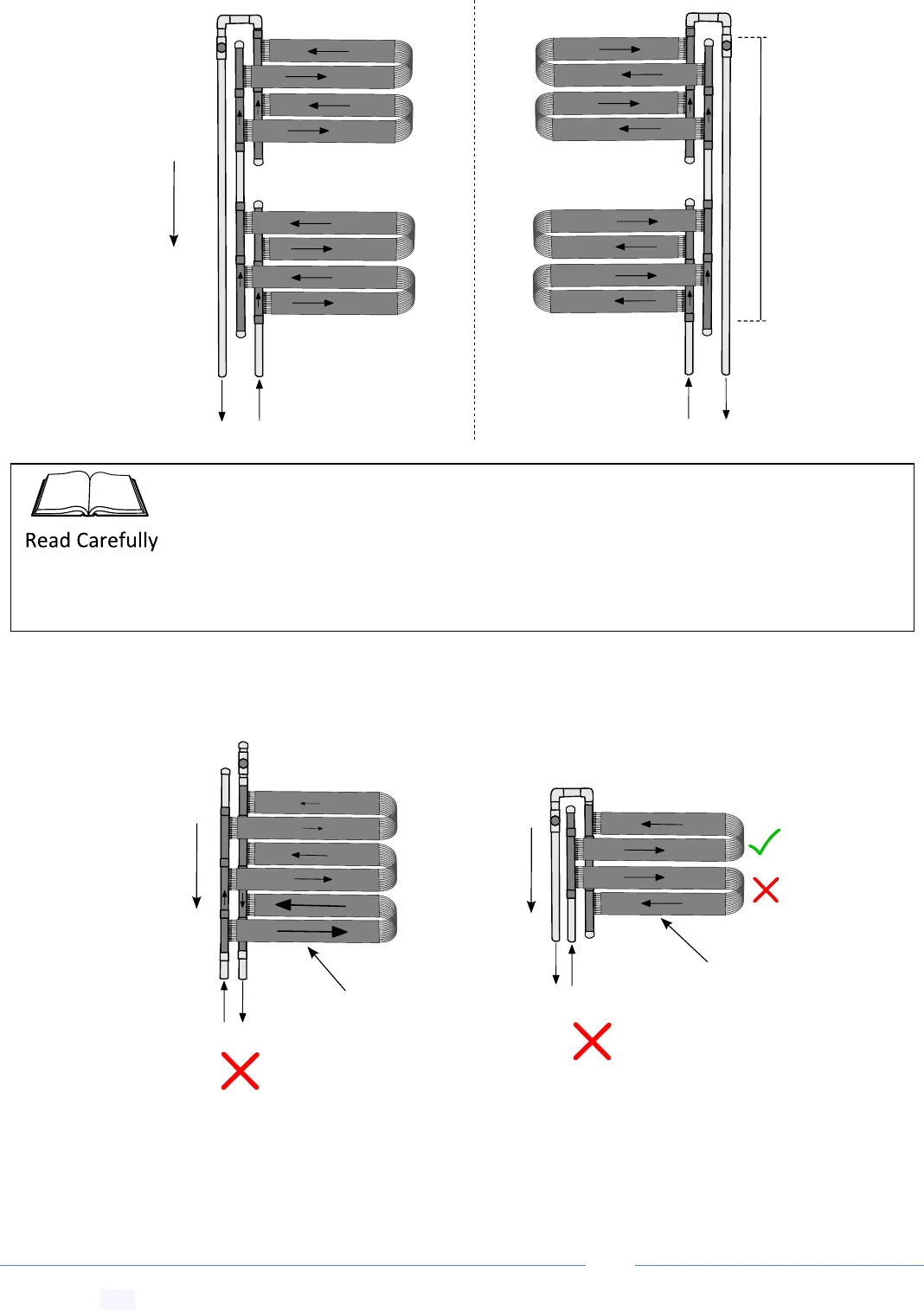
13.15 Bottom Feed In-Series Split Arrays (Low Pitch Roof Only)
Create jump link to this section-- Get Link
13.16 Plumbing Configurations Not Recommend
Create jump link to this section-- Get Link
Mirror Image
roof
slope
fall
max
height
diff
2m
It is preferred that
water is always
introduced into the
lower tube and
returns higher, not
the other way as
shown in bottom run
Without the third
pipe water always
takes the shortest
path, reducing
flow in the higher
tube strips
roof
slope
fall
roof
slope
fall
An “in series” configuration can be installed when you need to split an array. However
note, for this configuration the bottom array will receive much greater pressure.
Depending on the height of the top array and the pump size, this could over-pressurize
the bottom array. We recommend this array is used only if the height difference
between the two arrays is no more than 2m.
PoolMaster
pro
™ Solar Pool Heating System -- Installation & User Manual
© Copyright 2021 Optex Solar Pty Ltd. All rights strictly reserved.
Page 24
Split flow arrays of
different size should have
substantially similar tube
length runs or more water
will flow through the array
with the lower pressure drop
Ball valve constriction on
supply side is required
roof
slope
fall
Split flow arrays should have
substantially similar tube length
runs or more water will flow
through the array with the lower
pressure drop
Ball valve constriction on
supply side is required
roof
slope
fall
PoolMaster
pro
™ Solar Pool Heating System -- Installation & User Manual
© Copyright 2021 Optex Solar Pty Ltd. All rights strictly reserved.
Page 25
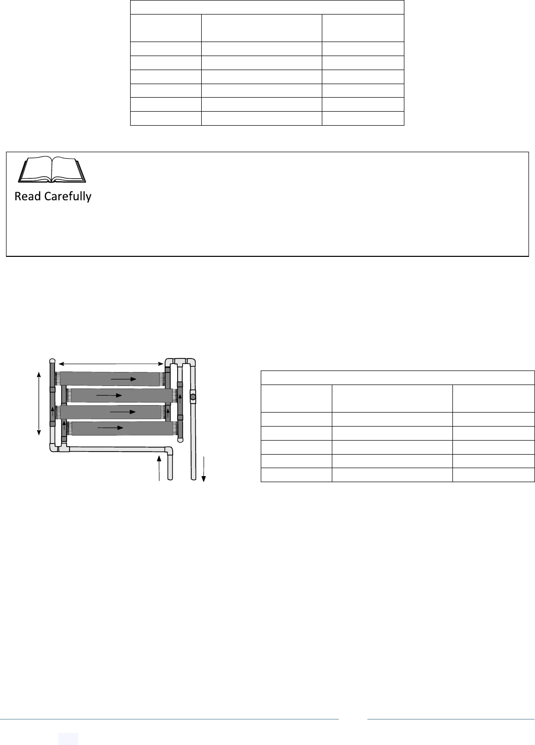
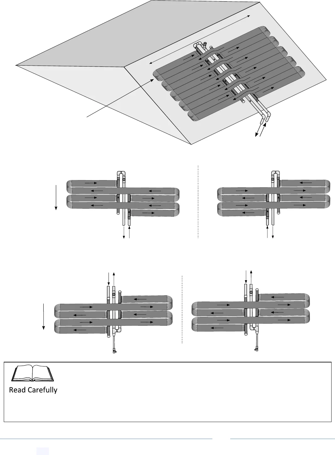
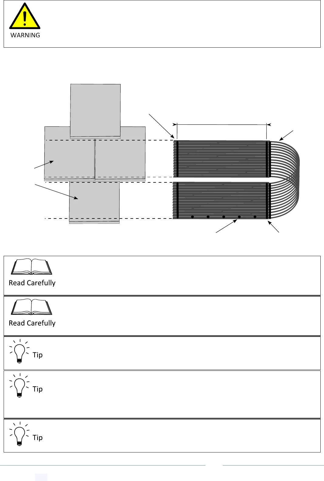
14 Adjusting Strip Spacing by Cutting Manifold
Create jump link to this section-- Get Link
For installations where the manifold assembly runs square up/down the roof slope, the spacing between collector
strips will need to be adjusted by cutting the manifold length to suit tile spacing, or other spacing requirements.
Manifold Length
Required Gap Between Strips
500mm (uncut)
60mm
480mm (2
nd
notch)
50mm
460mm (4
th
notch)
40mm
440mm (6
th
notch)
30mm
420mm (8
th
notch)
20mm
400mm (10
th
notch)
10mm (minimum gap)
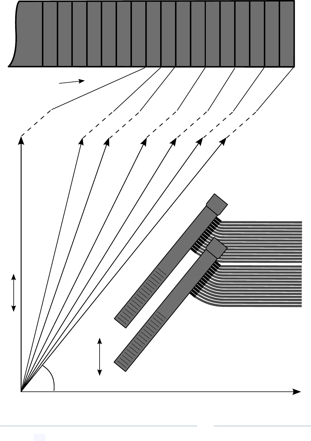
15 Adjusting Strip Spacing for Angled Manifold Runs
Create jump link to this section-- Get Link
For installations where the manifold assembly needs to run at an angle to the slope of the roof, the spacing
between collector strips will depend on the manifold angle and manifold length. The template on the next page
shows the manifold length required for 10mm strip spacing at a required manifold angle.
165mm
450mm
50mm
60mm
450mm
165mm
60mm
500mm
Uncut Manifold Gap
Uncut manifold
Uncut Manifold Gap
Glue a couple of manifolds first and then check the length on the roof. Length may need to
be adjusted for subsequent manifold additions.
PoolMaster
pro
™ Solar Pool Heating System -- Installation & User Manual
© Copyright 2021 Optex Solar Pty Ltd. All rights strictly reserved.
Page 26
no cut
10th notch
Collector tube strips run horizontal
Manifold angle required
Manifold angle required
9th notch
8th notch
6th notch
4th notch
2th notch
PAGE TEMPLATE - Manifold angle & length required for 10mm strip spacing
Roof slope
Manifold length
required
Roof
slope
PoolMaster
pro
™ Solar Pool Heating System -- Installation & User Manual
© Copyright 2021 Optex Solar Pty Ltd. All rights strictly reserved.
Page 27
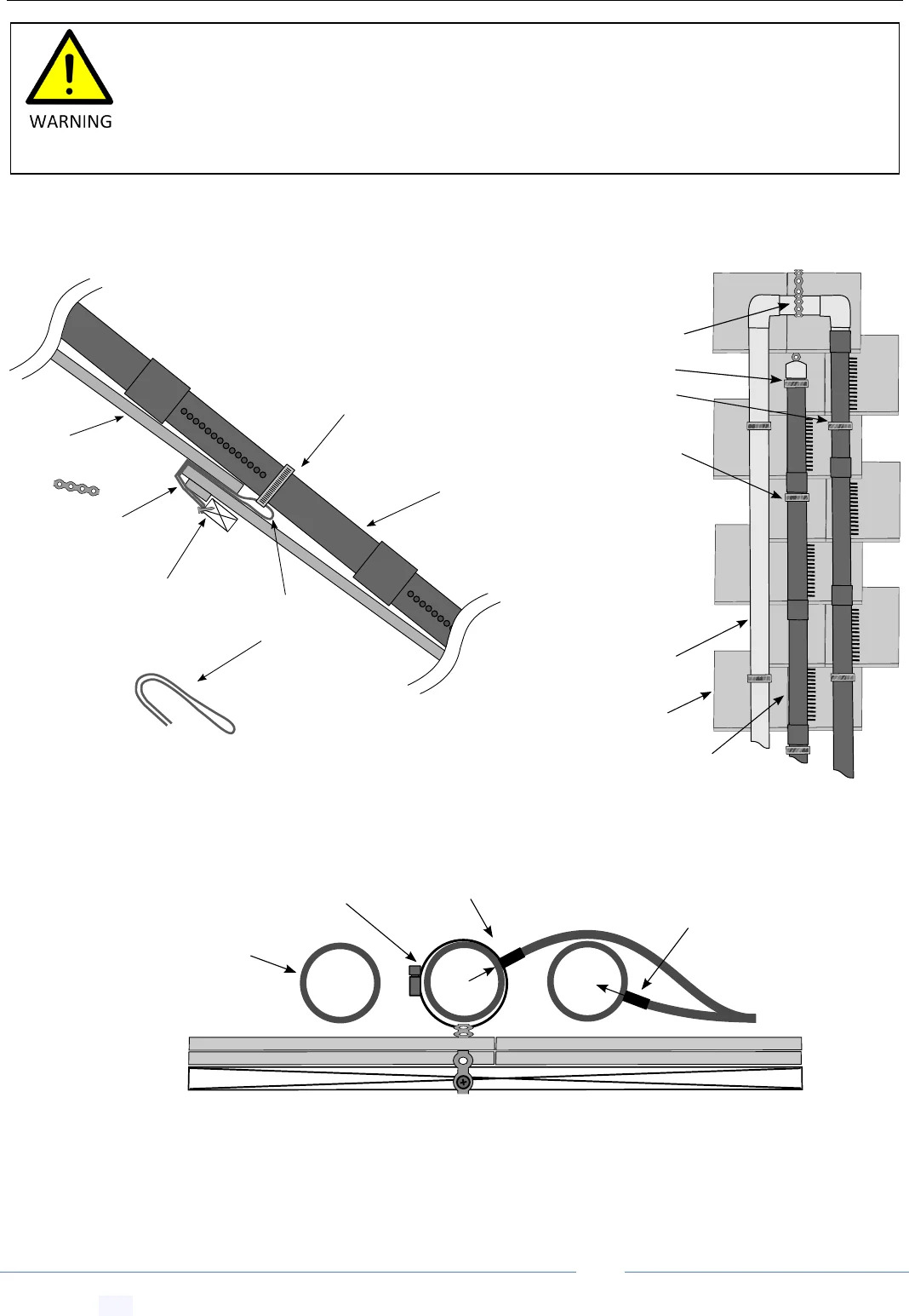
16 Roof Assembly and Attachment
Create jump link to this section-- Get Link
16.1 Tile Roof Mounting of Manifold Assembly
Create jump link to this section-- Get Link
Use perforated
band supplied or
hoop iron
Screw perforated
band loop into
batten
Fold band to
to create slip
loop
14 Tube
40mm
manifold
Roof tile
Do not over tighten clamps, allow
slippage for thermal expansion
14 Tube 40mm manifold
TOP VIEW
Return pipe
SIDE VIEW
Roof tile
Angle barbs on the
return down
Angle barbs on
the supply up
Return pipe
SIDE VIEW
Hose clamp
Secure all pipes
at choke points
just below a
pipe join or
manifold barbs
such that they
can't slip down
the roof
When working with power or hand tools always follow the safety instructions. Wear the
recommended personal protective apparel. Make sure electrical cables are kept away from
any water and from foreign objects which pose a potential cable severing or crushing hazard.
When using glues, solvents or sealing agents make sure you know and seek the proper first
aid in case of an accident.
PoolMaster
pro
™ Solar Pool Heating System -- Installation & User Manual
© Copyright 2021 Optex Solar Pty Ltd. All rights strictly reserved.
Page 28
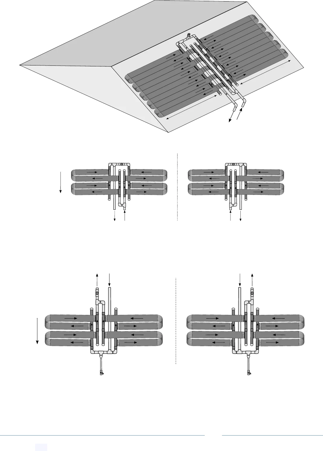
16.2 Corrugated Metal Roof Mounting of Manifold Assembly
Create jump link to this section-- Get Link
Do not over tighten clamps, allow
slippage for thermal expansion
Create diagonal support lattice using
supplied perforated band only
TOP VIEW
PERSPECTIVE VIEW
Return pipe
Always screw to crests
of roof structure
(seal well with silicon)
Secure all
pipes at
choke points
just below a
pipe join or
manifold barbs
such that they
can't slip down
the roof
Angle barbs on the
return down
Angle barbs on
the supply up
Perforated band
support lattice
Roof valleys must be keep clear
to allow passage of debris and water
self tapping
screws allowed
Return pipe
SIDE VIEW
Seal with
silicon
PoolMaster
pro
™ Solar Pool Heating System -- Installation & User Manual
© Copyright 2021 Optex Solar Pty Ltd. All rights strictly reserved.
Page 29
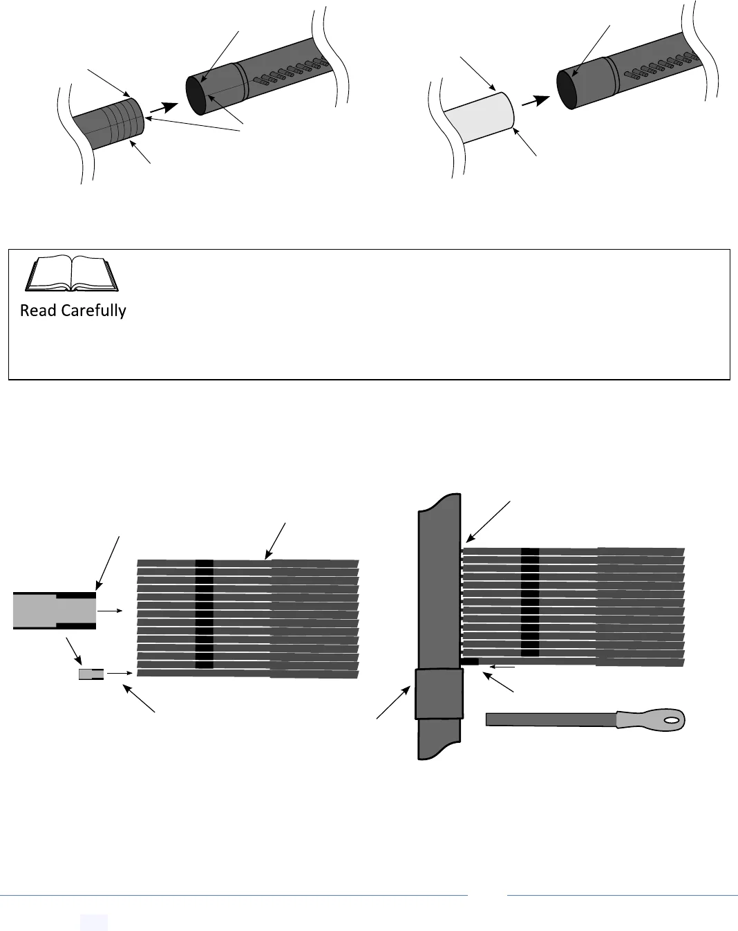
16.3 Manifold Gluing Procedure
Create jump link to this section-- Get Link
16.4 Connecting the Tubes to the Manifold Barbs
Create jump link to this section-- Get Link
Manifold to Manifold
Manifold to PVC
Cut to length, de-burr
and wipe clean, but
DO NOT use solver
primer
Cut to length and de-burr
use solvent primer
on PVC
Align tool mark
Apply 50mm depth N-type cement to
male part only, ensure full radial coverage
DO NOT apply any solvent
or cement to female part
DO NOT apply any solvent
or cement to female part
Apply 50mm depth N-type cement to
male part only, ensure full radial coverage
Cut tubes to length
and strip the connecting
webbing back ~30cm
Spray and wipe silicon lubricant on and
around the barbs and slide tubes on
Spray and wipe silicon on tubes
14 Barb
manifold
Tip! turn the manifolds barbs facing up. Slide
collars on by pressing them down using use
a flat metal file inserted between the tubes
Thread the smaller inner diameter
toward tubes
Observe: locking collar
has two inner diameters
Use N-type cement only for manifolds and the vacuum release valve. Never apply
primer or cement to any manifold female part. Work quickly, inert male part into female
socket immediately after cement application. Twist one way then the other to spread
any glue, align tool marks and hold in place for a moment. Wipe any excess to prevent
cement induced stress cracking.
PoolMaster
pro
™ Solar Pool Heating System -- Installation & User Manual
© Copyright 2021 Optex Solar Pty Ltd. All rights strictly reserved.
Page 30
16.5 Strip Collector Assembly and Gluing
Create jump link to this section-- Get Link
Silicon should be run
down the tile/collector
contact points
Strip
connecting
webs to fold
over for
return leg
Double silicon bead
near end uplift points
Run a silicon bead 6mm in diameter
every 400mm of collector strip
(more frequent for Wind Regions B, C & D)
For tiles
run the
160mm wide
strip along
tile terrace,
not over
tile steps
Secure edges of collector array using silicon
dots to guard against edge uplift
Ensure roof is clean and dry. Any moss will need to be removed using a high pressure
stray. Use supplied silicone adhesive. If you run out, the brand “Parafix” outdoor silicon
can be used as an alternative and is available at most hardware stores.
When stripping the return leg, use a blunt flat head screwdriver to press holes through
weak point in one side of the webbing first. Use needle nose pliers to pull out webbing.
Consider the passage of water under the collector. Make sure water can still drain and
run under the collector. On very flat tile you will need to lay a vertical strip of spare
collector tube at periodic lengths to allow drainage under the collector strip.
When gluing the strip start from the manifold. Glue the first part then place a couple of
heavy objects such as a brick on an unglued part to stop the glued side of the strip from
being disturbed as you lift the next part of the strip to run silicon under. Move the bricks
along as you glue the next part.
If you make a mistake and you need to remove the locking collar use a hair dryer or heat
gun to warm the tube. For extra grip use a piece of sand paper around the tube to pull off.
Take care not to overspray silicon on a critical part of the roof as this will create poor silicon
glue adhesion and a dangerous slippery working environment. Spray toward the manifold
assembly piping only - NOT toward the outgoing tubes. We recommend you use a cloth and
clean your hands regularly.
PoolMaster
pro
™ Solar Pool Heating System -- Installation & User Manual
© Copyright 2021 Optex Solar Pty Ltd. All rights strictly reserved.
Page 31
16.6 Alternate Strip Tile Layout for Short or Long Ledge Tiles
Create jump link to this section-- Get Link
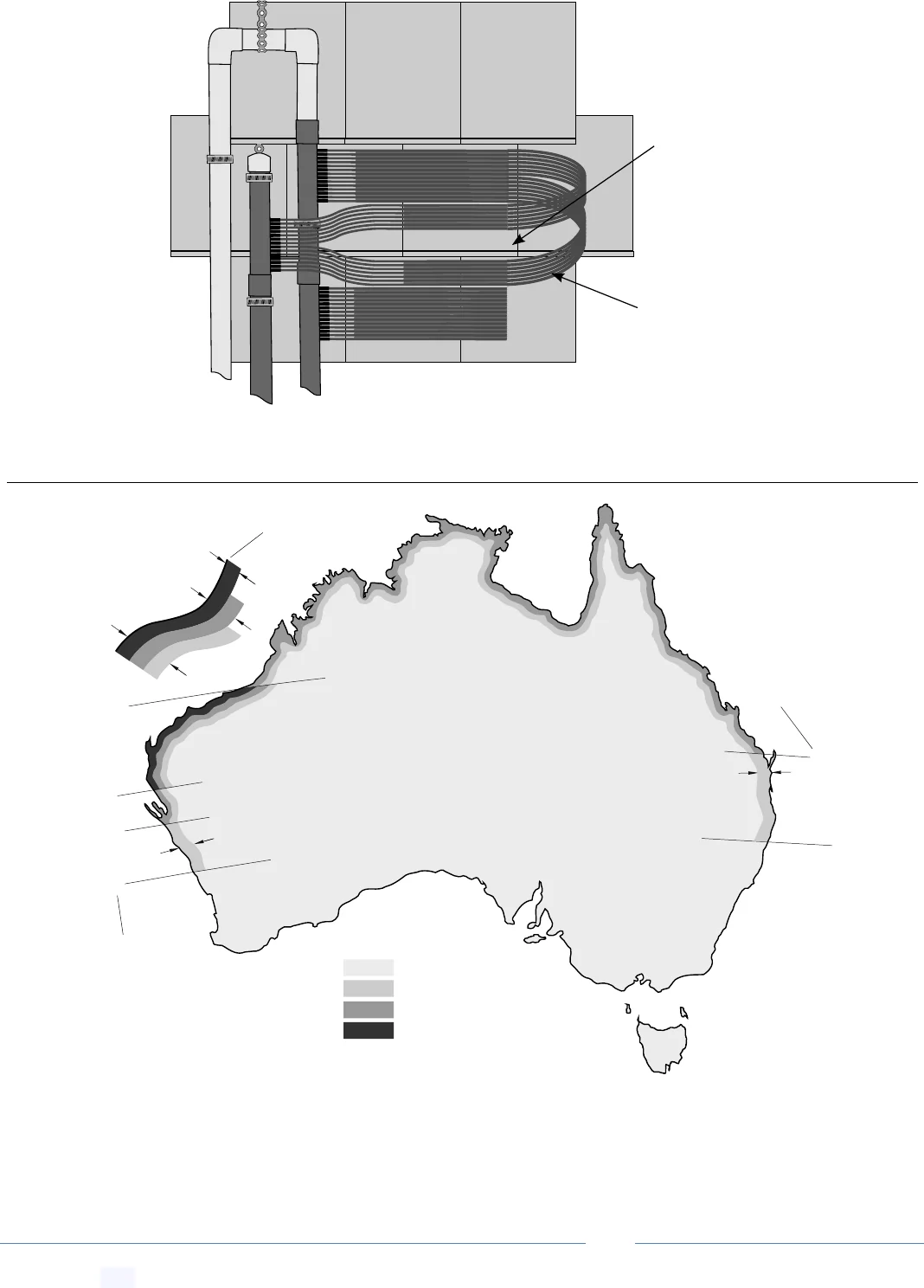
17 Extra Wind Proofing
Create jump link to this section-- Get Link
Coastal region boundaries are smooth lines set in from a smoothed coastline by 50km, 100km or 150km lines. If you
are in Wind Regions B, C or D, or situated on a hill or in open terrain, you will need to increase the above specified
frequency of fixings.
Split strip into
two to fit onto
tile short tile
ledge
Strip webbing
back 1m for
easy loop
back arrangment
and wind loadings
25°
30°
30°
20°
25°
27°
Latitude
Latitude
Wind Region D
Wind Region C
Wind Region B
Wind Region A
100km
100km
100km
50km
150km
Smoothed
coastline
PoolMaster
pro
™ Solar Pool Heating System -- Installation & User Manual
© Copyright 2021 Optex Solar Pty Ltd. All rights strictly reserved.
Page 32
17.1 Roof Edge Exclusions Zones
Create jump link to this section-- Get Link
Higher wind loading zone
Observe edge exclusion
Installation
zone
Edge Exclusion Zone
Edge Exclusion Zone
Edge Exclusion Zone
Edge Exclusion Zone
Note: Strips installed near or within a roof edge exclusion zone require 2 X the fixing strength
in that local area. Strips installations within a roof corner exclusion zone require 3 X the fixing
strength in that local area.

PoolMaster
pro
™ Solar Pool Heating System -- Installation & User Manual
© Copyright 2021 Optex Solar Pty Ltd. All rights strictly reserved.
Page 33
18 Collector Installation Order and Procedure
Create jump link to this section-- Get Link
1) Measure roof and plan out your installation using a diagram first.
2) Lay a few manifolds and collector ends out on the ground and measure where you need to cut them so that
they align with the collector strips.
3) If your manifolds run at an angle you’ll need to check the angle on the roof using the supplied template (see
above) to get the correct manifold spacing.
4) Cut and glue manifolds checking spacing as you go.
5) Lay the two completed manifold assemblies on the roof. In the appropriate place create the looped roof
attachment points for tiles, or perforated band diagonal supports for metal roofs.
6) Lay the manifold on the perforated band attachments and fix loosely at first using hose clamps.
7) Lay the collector strips out.
8) Cut the collector strips near the base of the respective barb manifold and connect the tubes to the barbs.
9) Glue remaining pipe work and vacuum release valve in place.
10) Tighten the hose clamps to secure the manifolds (while still allowing for some thermal expansion).
11) Drill 8.5mm hole and install pressure gauge on supply line using grommet.
12) Allow 24 hours for the glue to set before pressurizing components.
13) Turn the system on for the first time and check for leaks.
14) Check pressure gauge you may need to reduce or increase pressure using PVC ball valves.
15) With the system running glue the collectors down (keep the system running/cool while the glue sets).
16) Install any remaining components.
Collectors laid on a flat surface can be walked on without damage. Do not step on a hot
collector with a roof fixing screw underneath it. Take extreme care to use non-slip shoes
and never walk on wet collectors, or just glued collectors.
PoolMaster
pro
™ Solar Pool Heating System -- Installation & User Manual
© Copyright 2021 Optex Solar Pty Ltd. All rights strictly reserved.
Page 34
19 Plumbing Diagram Configurations
Create jump link to this section-- Get Link
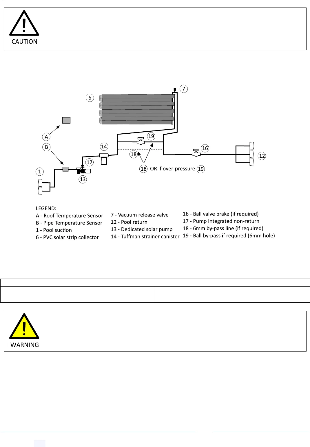
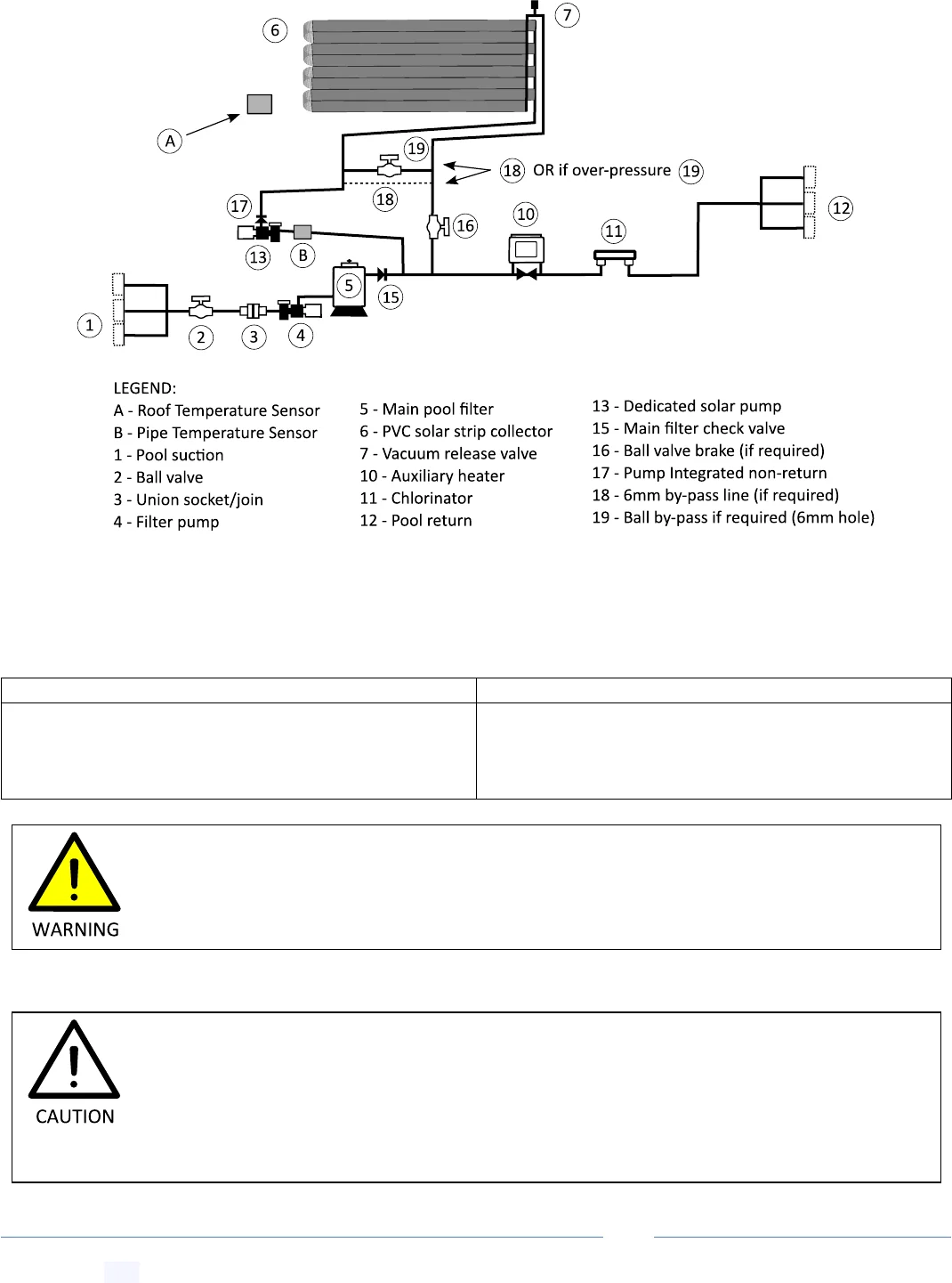
19.1 Configuration 1: Independent/Separate System
Create jump link to this section-- Get Link
Notes: Solar pump can run independently of the filter pump. A and B are the recommended temperature sensor
installation zones for the controller
Advantages:
Disadvantages:
* More energy efficient as a small solar pump runs
independent of the large main filter pump
* Requires separate solar suction provisions to be
installed
When constructing pipe work consider the thermal expansion of long lengths of pipe work
and the stress this produces on joins. Note: the minimum spacing for PVC 40 pipe supports
is 900m, less for smaller pipes. Use the perforated band to create saddles.
This system requires separate/independent Australian Standard approved suction and
return lines going into your pool. If you need to retro fit these you must contact a pool
builder.
PoolMaster
pro
™ Solar Pool Heating System -- Installation & User Manual
© Copyright 2021 Optex Solar Pty Ltd. All rights strictly reserved.
Page 35
19.2 Configuration 2: Integrated Independent System
Create jump link to this section-- Get Link
Notes: For pool with only 1 return port, the filter pump must be set on a timer to run outside of solar hours to
exclude the possibility of the two pumps running together. A and B are the recommended temperature sensor
installation zones for the controller
Advantages:
Disadvantages:
* More energy efficient as a small solar pump runs
independent of the large main filter pump
* Can be retrofitted to older pools depending on access
to underground suction line
* Pumps can’t run simultaneously for pools with only 1
return port.
* Suction tees above or only just below the water line
will require regular maintenance of non-return valves
19.3 Notes on Teeing into the Suction Line for Configuration 2
Create jump link to this section-- Get Link
If the pool has more than one return port and the filter pump and solar pump run together,
the installer must check the combined flow does not exceed suction inlet flow rate limits.
checked.
Note: the tee into the suction line must be performed far below the waterline (> 1m).
Why? When the filter pump starts it will create negative pressure in the suction line which
will drop the water line in the solar suction line - if the water line drops below the tee point
air will be drawn de-priming the main filter pump.

PoolMaster
pro
™ Solar Pool Heating System -- Installation & User Manual
© Copyright 2021 Optex Solar Pty Ltd. All rights strictly reserved.
Page 36
If the tee can’t be installed more than 1m below the waterline, or if it can only be installed above the waterline,
some installers will put in a perfectly sealing non-return on the solar line to stop the main filter pump de-priming.
Please be aware, this is a special valve with a polished ball and rubber seat, contact us at info@ecoonline.com.au if
you require it. A standard flap non-return will not suffice. Also note, such a system will need regular careful
maintenance of the solar and filter line non-returns. Any failures or even the smallest leaks in these non-returns, due
to twigs or grit getting into the rubber seal, will pass air and eventually de-prime pumps.
Solar suction tee
should be as far as
possible below
the waterline
approx 1m
Waterline
Filter pump
Solar pump
De-prime Senerio
If either pump turns
ON and drops the water
level in the opposing
suction lines to the
tee level - then air will
enter the suction line
and deprime that
pump
A special perfectly
sealing non-return
will be required
to fix de-priming
(installed
downstream
of any filter or
strainer)
Fine strainer
Filter
Non-perfectly sealing
non-return flap
PoolMaster
pro
™ Solar Pool Heating System -- Installation & User Manual
© Copyright 2021 Optex Solar Pty Ltd. All rights strictly reserved.
Page 37
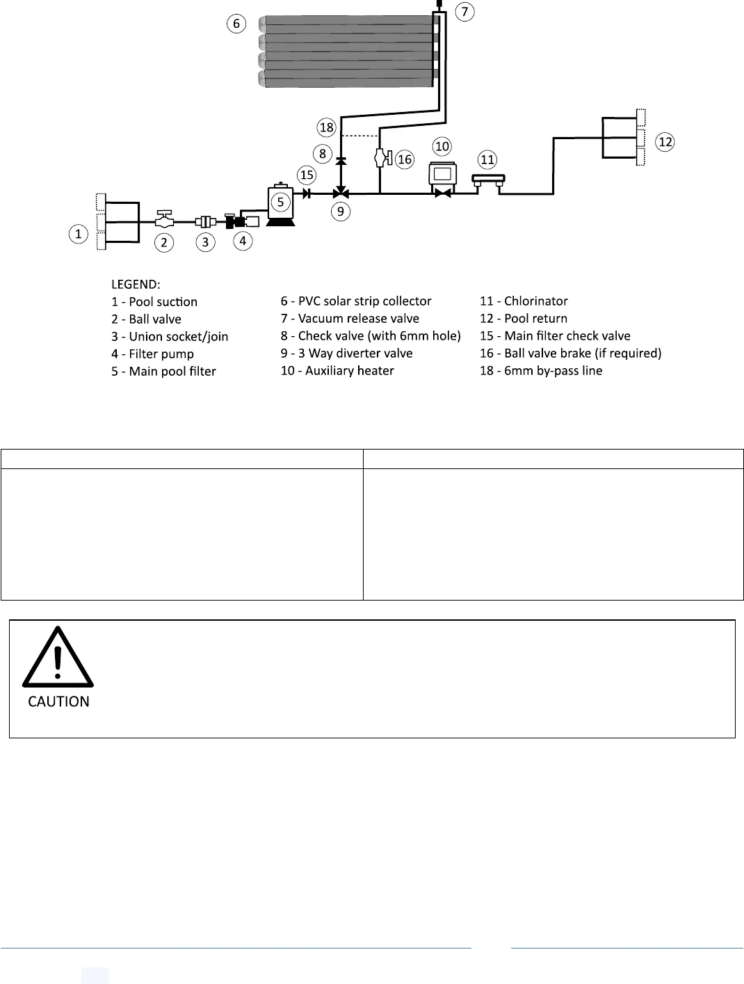
19.4 Configuration 3: Manual/Timer/ Motorized Valve System
Create jump link to this section-- Get Link
Notes: Manual or motorized three-way valve (9). (Note: automatic controls are omitted for clarity).
Advantages:
Disadvantages:
* Manual system requires no extra pump required
* Manual system, needs to be turned off/on or on a timer
* Only filtered water runs through collectors
* Large main filter pump needs to run all day for solar
* Can be retrofitted to pools that don’t have separate
solar provisions
* Motorized three-way valve and controller can be
retrofitted later
* Requires specialized motorized valve and controller to
automate
* Increases pressure and decreases flow rate in the filter
system
* Not recommended for two story installations
For manual pool heating systems running off a main pool filter pump, please check that the
pump is large enough to accommodate the extra load of supplying water to the collectors
at the required pump height. Generally, this configuration is not recommended for two
story or greater installs.
PoolMaster
pro
™ Solar Pool Heating System -- Installation & User Manual
© Copyright 2021 Optex Solar Pty Ltd. All rights strictly reserved.
Page 38
19.5 Configuration 4: Booster/Retrofit System
Create jump link to this section-- Get Link
Notes: Solar booster pump locked to run with filter pump - requires specific controller Dontek V7RTS. Solar pump
(13) should of lower flow than filter pump (4). A and B are the recommended temperature sensor installation zones
for the controller
Advantages:
Disadvantages:
* Less extra plumbing is required for solar
* Requires second pump and special controller
* Only filtered water runs through collectors
* Does not require separate solar suction provisions
* Large main filter pump + solar pump need to run all
day for solar
This configuration is not recommended for single story installs for pools with only a single
return port due to the potential over pressurization of the panels when both pumps run at
the same time. However for two story or greater installs, even with a single return port, this
is the recommended configuration for pools that don’t have separate suction ports.
PoolMaster
pro
™ Solar Pool Heating System -- Installation & User Manual
© Copyright 2021 Optex Solar Pty Ltd. All rights strictly reserved.
Page 39
19.6 Installing the Strainer for Independent Systems
Create jump link to this section-- Get Link
Install the Tuffman strainer canister as shown in the plumbing diagram above
with the clear side down. If the strainer is installed below the waterline you
should install a PVC ball valve to isolate the strainer for cleaning purposes.
Depending on the level of pool use and debris in the pool the strainer may
need to be cleaned regularly. Use a jet of water.
20 Installing the Controller for Independent Systems
Create jump link to this section-- Get Link
Please refer to the controller manual as different controllers have specific installation instructions. Here we only add
supplemental instructions; they should not override any specific controller instructions. Note: controller manuals are
downloadable from the EcoOnline.com.au website.
20.1 Installing the Roof/Hot Sensor
Create jump link to this section-- Get Link
If your controller comes with a long 20m cord hot roof sensor it should be adhered using silicon to a sun exposed
roof tile or section of corrugated metal roof. It should NOT be installed, on top off, inserted into, or under the
actual PVC collector strips. Ideal placement is within arm’s length of the gutter.
20.2 Installing the Pool/Cold Sensor
Create jump link to this section-- Get Link
The cold sensor should be fitted inside a section of PVC suction line (before the solar pump) and sealed using the
grommet supplied. For this you will need to drill a hole in the suction line, please check the controller manual for the
recommended size.
Standard unmodified drill bits have “positive rakes” and can easily “bite into” soft
materials. This can cause a sprain injury as a hand drill will violently kick and spin. Drill bits
can easily be modified to “zero rake” to prevents this, see
https://www.youtube.com/watch?v=pAngKHIZgyA. Alternately, a step drill bit or a
standard drill bit spun backwards can be used. A cone shaped rolled up piece of sandpaper
can be used to even out or increase the diameter of the hole to size.
If the cord is too short the sensor can also be located on any unshaded “roof proxy”
surface that faces the same part of the sky as the collector strips to approximate the
surface temperature of the roof itself. Alternatively, it can be extended see below.
PVC plastic should be preheated to 50˚C using a heat gun to prevent it from splitting
during drilling. We recommend you practice on a pipe off cut before attempting the hole.
PoolMaster
pro
™ Solar Pool Heating System -- Installation & User Manual
© Copyright 2021 Optex Solar Pty Ltd. All rights strictly reserved.
Page 40
20.3 Extending Sensor Cords
Create jump link to this section-- Get Link
The sensor cords can be extended using similar type cord but in a larger gauge wire. Note, the Dontek cold sensor
uses a shielded type cord; hence you will need the same type (but in a higher gauge) if extending it. Please contact
Dontek or Ascon if unsure.
21 Drain-Down, Frost Proofing and Winterization
Create jump link to this section-- Get Link
21.1 Drain Down
Create jump link to this section-- Get Link
All pool heating systems have a drain down design and MUST drain as fully as possible when the system stops.
21.2 Winterization
Create jump link to this section-- Get Link
Your collector strips as well as your solar booster pump will require regular winter flushing, you should make sure
the controller you have has a winter mode. If you do not want to run your system over winter you can winterize your
system by draining the solar side of the system, disconnecting the solar booster pump and flushing the pump with
clean water for storage over winter.
The use of a water tight non-return valve on the solar supply will prevent drain down
which could result in water freezing inside PVC piping in frost prone areas and/or hot
water stagnation in summer. Any non-return valves installed on the supply line MUST
have a 6mm drain hole drilled in the flap to allow drain down. Why? The main purpose
of the non-return valve is to prevent a large volume of water from spinning the pumps
rotor backwards when the pump stops. A 6mm hole allows slow drain down while also
preventing hammer action in the flap when the pump stops.
PVC piping should be installed with a slope such that all water drains out of the piping to
when the pump stops to ensure a freeze proof system. There should be no U-bend water
traps - these can freeze over and burst plumbing lines in the winter. Note: PE lines are not
affected as these are frost impervious.
When extending the cord, we recommend a “lap splice” solder join with adhesive heat shrink.
Solder joins should not be placed in any conduit section running under ground.
PoolMaster
pro
™ Solar Pool Heating System -- Installation & User Manual
© Copyright 2021 Optex Solar Pty Ltd. All rights strictly reserved.
Page 41
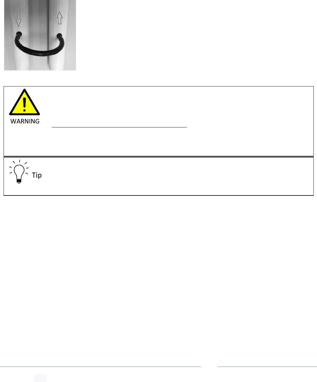
21.3 Installing a By-Pass Tube or By-Pass Ball Valve
Create jump link to this section-- Get Link
A drain tube (18) or a by-pass ball valve (19) with 6mm hole can be used to drain non-self draining sections of PVC
piping in frost prone areas. In some cases where there are issues with pump priming and a perfectly sealing non-
return valve (8) is required; the aforementioned by-pass lines can be installed on the supply and return solar lines
leading up to the roof approximately one metre above pump level to reduce priming pressure. Please request this
component if you require it.
To install, drill into the PVC pipe using a modified “zero rake” 8.5mm drill bit. Insert the
rubber grommet into the hole first, and then insert the single barb side barb into the
grommet. Finally connect the by-pass tube to the double barb side barb ends.
Standard unmodified drill bits have “positive rakes” and can easily “bite into” soft
materials. This can cause a sprain injury as a hand drill will violently kick and spin. Drill bits
can easily be modified to “zero rake” to prevents this, see
https://www.youtube.com/watch?v=pAngKHIZgyA. Alternately, a step drill bit or a
standard drill bit spun backwards can be used. A cone shaped rolled up piece of sandpaper
can be used to even out or increase the diameter of the hole to size.
PVC plastic should be preheated to 50˚C using a heat gun to prevent it from splitting
during drilling. We recommend you practice on a pipe off cut before attempting the hole.
PoolMaster
pro
™ Solar Pool Heating System -- Installation & User Manual
© Copyright 2021 Optex Solar Pty Ltd. All rights strictly reserved.
Page 42
22 Optimizing Collector Pressure
Create jump link to this section-- Get Link
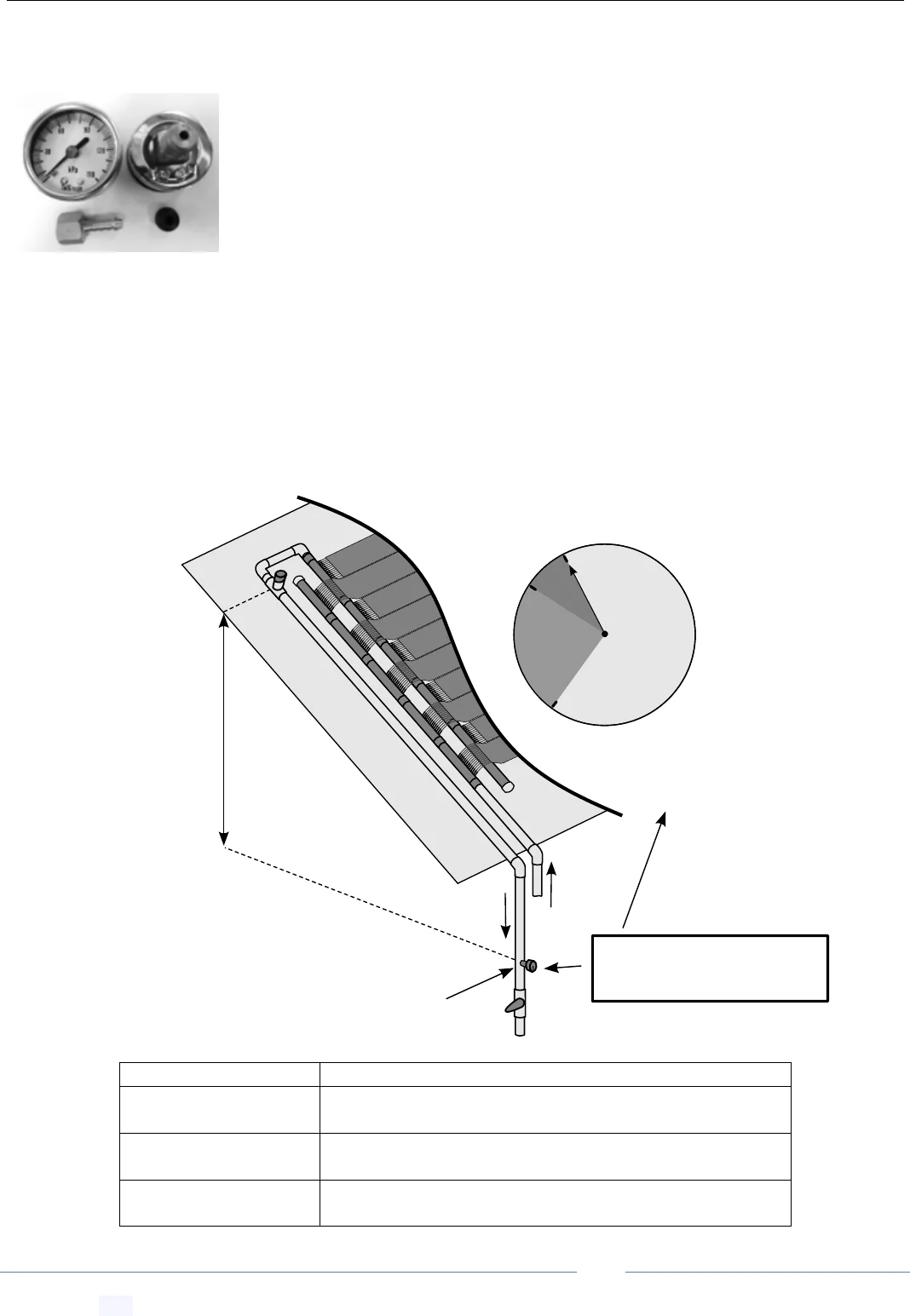
22.1 Installing the Pressure Gauge
Create jump link to this section-- Get Link
The pressure gauge must be installed on the return line preferably near eye level. Drill
into the PVC pipe using an 8.5mm drill. Insert the rubber grommet into the hole
tapered end first. Use pink Teflon tape on brass tread, lubricate the brass barb with
silicon spray prior to insertion into the grommet. Note: PVC plastic should be
preheated to 50˚C using a heat gun or it may split when drilling.
22.2 Pressure Check Procedure
Create jump link to this section-- Get Link
To make pressure adjustment depending on over-pressure or under-pressure situations, you’ll need to install either
a ball by-pass valve (19) to reduce pressure or a ball break valve (16) on the return line to increase back pressure
(both at near ground level for easy adjustment). Manual type systems need only the adjustable 3-way ball valve.
Collector pressures can then be adjusted as follow:
Gauge Pressure
Pressure Adjustment Advice
Less than:
head pressure + 5 kPa
Install ball valve brake (16) (see plumbing diagrams) to
increase back pressure in return line
About equal to:
Head pressure + 5 kPa
Pressure is ideal no action required
Greater than:
head pressure + 5 kPa
Excessive pressure - install extra pool returns or remove
eyeballs from returns, or install by-pass (19) with ball valve
To
pool
Ideal gauge pressure:
vertical head pressure + 5 kPa
Pressure gauge is mounted
above the break ball valve
28 kPa
23 kPa
head
pressure
5kPa
example
reading
example
reading
From
pool
0 kPa
For a 2.3m head pressure
pressure gauge should read:
23 kPa + 5 kPa = 28 kPa
Head Pressure :
Vertical measure
from vacuum
release to
pressure gauge
Note: 1m head pressure = 10 kPa
PoolMaster
pro
™ Solar Pool Heating System -- Installation & User Manual
© Copyright 2021 Optex Solar Pty Ltd. All rights strictly reserved.
Page 43
22.3 Negative Pressure and Air Bubble Issues
Create jump link to this section-- Get Link
If the pump height is substantial and/or you have more than one return outlet to your pool, it may be that your
pump cannot positive pressurize the vacuum release valve. In this case you will get undesirable constant bubbling in
the outlet to the pool as the vacuum release valve is at negative pressure and is drawing in air. If this happens you
will need to install the down draft/brake PVC ball valve (16) on the return line (see plumbing diagrams) and carry out
the following procedure:
Start the system and wait for it to settle.
1) Constrict flow in the return line using the ball valve brake (16, see plumbing diagrams) lever handle by a
small increment.
2) If after some time the air bubbling continues, constrict flow by another small increment.
3) If air bubbles stop reliably at this point, then the vacuum valve is now at the required positive pressure, the
pressure gauge should read a value near the head pressure (vertical distance from vacuum release and
pressure gauge) + a few kPa’s, this is ideal.
4) Leave the ball valve brake at this setting/constriction permanently (remove handle).
5) If the required constriction is greater than 50% you will need a stronger pump.
22.4 Adjusting the 3 Way Valve for Manual Systems
Create jump link to this section-- Get Link
The following procedure for a manual system need be carried out only once during installation.
1) Open the three way ball valve (9, see plumbing diagrams) using the lever handle by a small increment.
2) Wait to see if there is sufficient flow and back pressure to create positive pressure at the vacuum valve (7).
3) If after some time air bubbling is still present in the return line, open the three way valve (9 see plumbing
diagrams) by another small increment.
4) If air bubbles stop reliably at this point, then the vacuum valve is now at the required positive pressure.
5) Fix in place a back stop on the ball valve lever handle at this travel point, as this will be your maximum
opening point for your three way valve when turning the heating system on again.
22.5 Optimizing Pressure for Oversized Pumps
Create jump link to this section-- Get Link
For an over-sized solar pump (13, see plumbing diagrams) we recommend the following procedure, carried out only
once during installation, to limit pressures inside the panels.
Over-sized pumps and flow rates could potentially limit the lifetime of your collectors due to
pressure working. Note, the return line to the pool MUST be unconstricted, with an
appropriate number of pool outlets so as not to create significant back pressure.
Use the below procedure for solving air bubbling issues, DO NOT remove or drop the
level of the vacuum release valve or increase pump strength. The vacuum release valve
MUST be mounted as specified to ensure collectors are not pressure worked.
PoolMaster
pro
™ Solar Pool Heating System -- Installation & User Manual
© Copyright 2021 Optex Solar Pty Ltd. All rights strictly reserved.
Page 44
1) Removed any potential constrictions in the return line going back into the pool such as eyeballs in the return
outlets.
2) If pressure is still too great (as measured at the pressure gauge, see above Pressure Check Procedure, install
a by-pass ball valve (19) (see plumbing diagrams).
3) Turn the solar pump on with the by-pass-ball valve fully open.
4) Constrict the by-ball valve in small increments until you get the correct pressure, see above.
5) Fix the by-pass ball valve handle in place by some means.
23 Checking for Balanced Water Flow
Create jump link to this section-- Get Link
At midday with the sun shining on the collectors and the pump operational, run your hand over every part of each
collector in the array. The collector tube near the supply should be cool to the touch while the tubes near the return
should be only slightly warmer to the touch. No part of any collector should be hot to the touch. Hot spots indicate
that there is no or little water flow through this part of the tubes.
During operation the outlet water flow should be strong with a temperature no greater
than about 5-7°C that of the inlet. Why? Faster flows rates will result in a lower
temperature difference across the collector array and hence will maximize collector
efficiency; however this should be balanced against electricity usage and maximum
allowable tube pressure.
PoolMaster
pro
™ Solar Pool Heating System -- Installation & User Manual
© Copyright 2021 Optex Solar Pty Ltd. All rights strictly reserved.
Page 45
24 Service and Maintenance Schedule
Create jump link to this section-- Get Link
Maintenance Issue - Service Procedure
Monthly
Quarterly
Annually
Strainer – Depending on pool usage and level of debris you may
need to clean the strainer regularly.
X
Leaks – A leak check should be performed as leaks can corrode
metal roofs and gutters. Any leak should be repaired.
X
Non-Return Valve – The non-return valve (8 see plumbing
diagrams) is a critical system component. It should be checked
that the 6mm hole drilled in the flap has not become blocked
and that the collectors drain fully when the pump stops.
X
Vacuum Release Valve – The vacuum release valve (7) is a
critical system component. It should be checked that it is not
weeping corrosive water onto the roof.
X
Plumbing Degradation – Plumbing should be checked for signs
of UV and/or chemical damage. Replace as needed.
X
Debris Accumulation – Check that there is no build up of debris
around pipe work or collectors, and that water has a clear path
to run down.
X
Winterizing System – You may need to prepare your system for
winter dormancy each year.
X
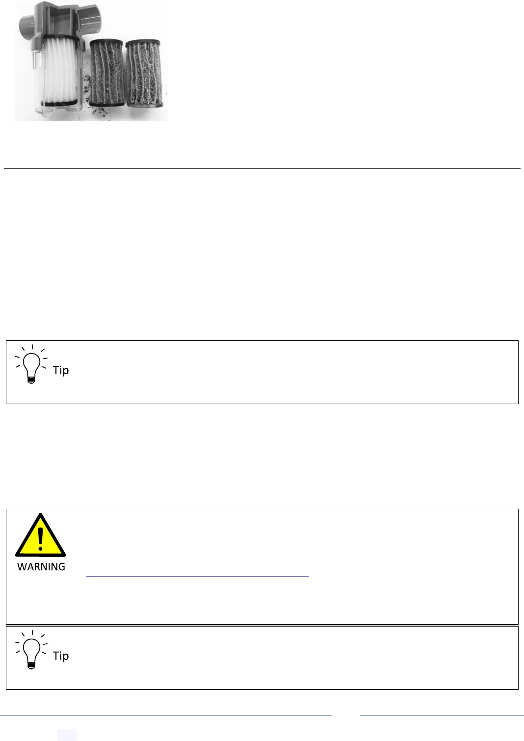
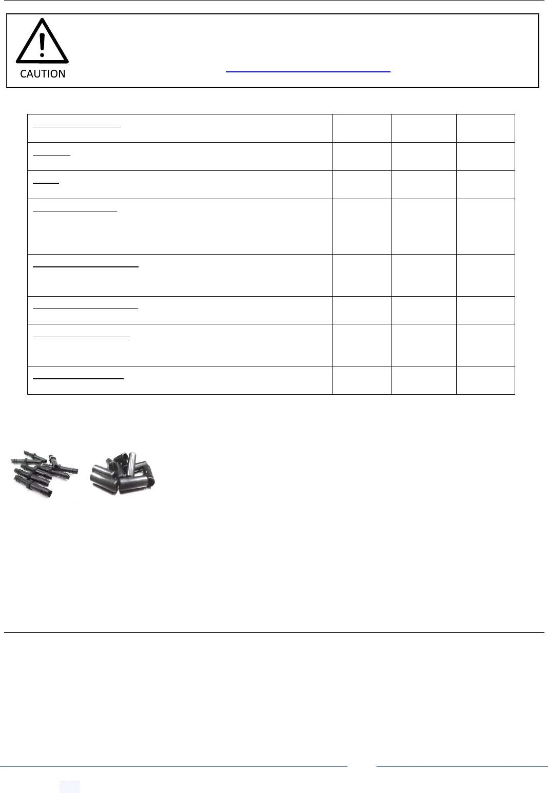
24.1 Collector Puncture Repair Procedure
Create jump link to this section-- Get Link
Locate the leak, cut a 3mm cross section of tubing, strip webbing, and thread the
locking sleaves. Lubricate barb joiner using silicon spray. Join tubes using the barb
connector. Lubricate and slide on locking collar, using a blunt object, such as the
back of a kitchen spoon.
25 User Information
Create jump link to this section-- Get Link
25.1 Notes on First Usage
Create jump link to this section-- Get Link
After the system is switched ON for the first time, please be aware that it will take up to 1 week for the pool and the
surrounding ground around the pool to warm up and come to a new temperature equilibrium. As such systems that
are used intermittently, for example on weekends only, will not result in pool temperatures as high as continuously
ON systems.
Important: before carrying out any system maintenance you MUST check for any manual
and or technical service bulletin updates and download the latest installation manual
from our Downloads Page: www.EcoOnline.com.au/downloads
PoolMaster
pro
™ Solar Pool Heating System -- Installation & User Manual
© Copyright 2021 Optex Solar Pty Ltd. All rights strictly reserved.
Page 46
25.2 Potential for Hot Water at the Outlet on Start Up
Create jump link to this section-- Get Link
26 Important Installation Check List
Create jump link to this section-- Get Link
Your installation should have the following elements:
Correctly sized pump or pressure optimization carried out.
A third balance pipe must be installed for all collector arrays.
For independent systems not going through the filter, the supplied strainer MUST be installed.
The supplied vacuum release valve MUST be installed on the roof on the return line.
Smooth flow is achieved; little air bubbling is present in pool after initial purging.
A hot spot check was performed. All tube lengths are cool during full sun exposure, indicating water flow.
A non-return valve was installed (with a small 6mm hole drilled in the flap).
The drain/equalization tube was installed on the supply and return line.
Collectors should run and be adhered to the top of ridges of any roof structure, not the valleys to allow water
and debris drainage.
Frost proofing was considered. All PVC lines are sloped such that water runs back into the pool at night.
Solar controller roof sensor was mounted on the roof and not on a solar collector.
Extra silicon adhesive was used for collectors near roof exclusion zones (near roof edges).
Pipes and manifold assemblies are mounted above roof valleys to allow clear drainage of water and debris.
The pressure gauge was installed on return line and the pressure optimization procedure was carried out.
User is aware of the maintenance schedule.
Users should be made aware that under rare conditions on system start up, very hot water
~ 60°C will be ejected at the outlet return ports which has the potential to scold swimmers.
Users (especially children) should be advised to keep away from outlet during start up.
Due to the potential for hot water at the outlet on start-up, solar heating outlets must not
be connected to water features or waterfalls, or any other outlet(s) that are not
permanently fixed underwater. Where practicable, solar heating systems shall be designed
to completely drain down. Where a solar heating system cannot be designed to drain
down, a water bypass or tempering device arrangement shall be installed prior to the solar
heating outlets into the pool. Contact info@EcoOnline.com.au for a recommended return
line water tempering configuration.